A nibbler table.
Sheet metal can be cut a number of different ways. I have tried using aviation snips, hacksawing, bandsawing, using abrasive discs and nibbling. Of these the use of a nibbler is by far the best. It is fast and gives little distortion at the cut edge. The problem with hand held nibblers is that they are quite difficult to control. I made some improvements to my small nibbler that is used as an attachment to an electric drill to make it easier to control and these are described here.
Of course the best way of cutting sheet metal is to use a large shear but these are expensive and take up much room.
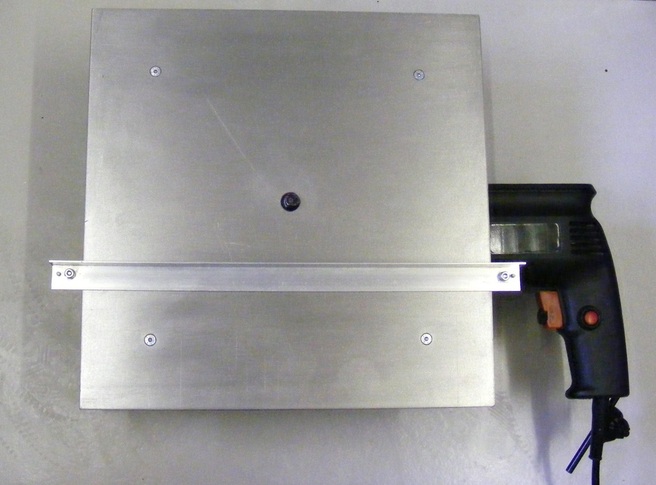
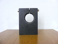
In order to improve the cutting accuracy I have made a table mounted nibbler. This is shown in the header Photo.
Of course the best way of cutting sheet metal is to use a large shear but these are expensive and take up much room.
In order to improve the cutting accuracy I have made a table mounted nibbler. This is shown in the header Photo.
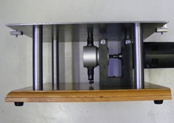
The nibbler table consists of a baseboard, a bracket to clamp the nibbler head and the electric drill, four pillars to support the table and the table itself.
The baseboard was a piece of solid oak 20 x 300 x 300mm. This was cut from an old kitchen cabinet door but plywood or MDF would be good alternatives.
The baseboard was a piece of solid oak 20 x 300 x 300mm. This was cut from an old kitchen cabinet door but plywood or MDF would be good alternatives.
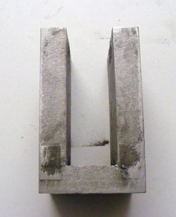
The bracket was made from a simple U shaped auluminium casting produced using the lost foam method. The casting was mounted in the mill vice ensuring all sides were vertical and the base was machined flat with a flycutter.
The bracket could also be built up from flat sections.
The position of the holes for the nibbler head and electric drill were marked out. These holes were cut undersize using a 38 mm holesaw.
The bracket could also be built up from flat sections.
The position of the holes for the nibbler head and electric drill were marked out. These holes were cut undersize using a 38 mm holesaw.
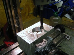
The bracket was then mounted in the mill vice for boring. A piece of thin MDF was placed between the base of the vice and the casting to prevent damage to the vice. Both the upper and lower holes were bored without unclampig the vice using a long boring bar in a boring head. This ensures that both holes are concentric.
After boring the bracket was drilled for the M6 clamping studs. First a 5 mm hole was drilled with a long series drill all the way through. This was opened out to 6.5mm for most of the way leaving about 12mm of the hole at 5 mm for tapping. The 5 mm section was tapped M6.
The clamp was slit using a 2 mm slitting saw and two holes drilled in the base for the holes securing the bracket to the baseboard.
The M6 clamping studs were screwed in and locked in place, on the left hand side adjacent to the threaded part of the hole, using M6 washers and nuts. Washers and clamping nuts were then screwed onto the right hand side.
The pillars were made from 20 mm round stock. One end was faced, drilled and tapped M5 for the screws securing the pillar to the baseboard.. It was parted off a little oversize. It was turned around in the chuck and the other end faced to give the correct length. This end was drilled and tapped M4 for the screw securing the table.
The table was made from a piece of steel plate 3 x 300 x 300. This was supplied cut to size. A 13 mm hole was drilled in the centre of the plate for the nibbler head. Four 4.5mm holes were drilled 50 mm from the adjacent sides at each corner. These holes were countersunk to accept M4 countersink screws.
The table was placed on and lined up with the edges of the baseboard and the four corner holes spotted through onto the baseboard. The marked positions on the baseboard were drilled out to 5.5 mm.
The table was placed on and lined up with the edges of the baseboard and the four corner holes spotted through onto the baseboard. The marked positions on the baseboard were drilled out to 5.5 mm.
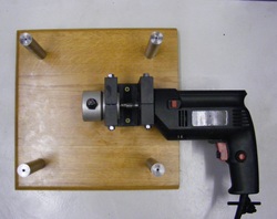
The four pillars are attached to the base board using M5 screws. The nibbler head was clamped into the bracket and the table lowered until the nibbler head protruded through the 13 mm in the centre of the table. The table was moved to locate the corner holes over the pillars and the table was secured in place with four M4 countersink screws. The bracket was aligned parallel with the edges of the baseboard and its position marked around with a scriber. The table was removed and the bracket carefully positioned within the scribed lines and the holes in the base spotted through to the baseboard. The marked positions were drilled with a 3mm drill and the bracket secured in place using 4x30mm woodscrews. The table was reassembled onto the pillars.
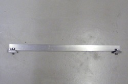
The fence was a length of 1.5 x 18 x 18 aluminium angle. Two steel clamps were made for each end.
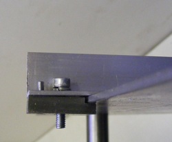
The end clamps were made from 6 x 16 x 25mm steel. One edge was recessed 2.6mm on the mill. The clamp is secured to the fence by a M4 screw into a tapped hole in the clamp. To the left of the screw can be seen a 2.5mm anti-rotation pin that is fixed in the clamp
