Autostop
Adding an autostop that stops the carriage movement at a particular point when the carriage is being motor driven is a great addition to the lathe. It is particularly useful when cutting to a shoulder. Having already fitted a small dc motor to the leadscrew (see leadscrew motor) I decided to use an electrical autostop system.
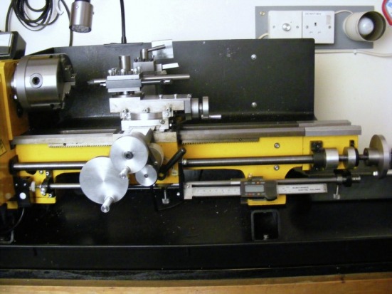
The photo above shows the modifications required. These were few since much of the hardware is common with the carriage DRO set up previously described. Focus on the long 10 mm rod, below the leadscrew, that carries the DRO. This rod is a little longer than the rod used initially for mounting the DRO. At the right hand end of the rod a spring has been added. At the left hand end of the rod a microswitch (housed in the small black box) has been added together with a knurled knob that actuates the microswitch. The spring on the right hand side ensures that the rod is biased to the right normally and the knurled knob does not actuate the microswitch. When the carriage moves to the left and hits the right hand stop collar then the carriage moves the rod to the left and this then actuates the microswitch.
The photo above shows the modifications required. These were few since much of the hardware is common with the carriage DRO set up previously described. Focus on the long 10 mm rod, below the leadscrew, that carries the DRO. This rod is a little longer than the rod used initially for mounting the DRO. At the right hand end of the rod a spring has been added. At the left hand end of the rod a microswitch (housed in the small black box) has been added together with a knurled knob that actuates the microswitch. The spring on the right hand side ensures that the rod is biased to the right normally and the knurled knob does not actuate the microswitch. When the carriage moves to the left and hits the right hand stop collar then the carriage moves the rod to the left and this then actuates the microswitch.
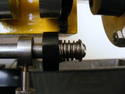
This shows the spring on the right hand end of the rod. The spring is nothing special and just happened to be in my "it might come in handy" box. It is retained on the end of the rod by a washer and a 6 mm screw as shown. The spring acts against the right hand support bracket for the bar and keeps the bar biased to the right until the carriage hits the the stop clamp which then moves the rod to the left against the pressure from the spring.
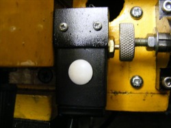
This photo shows the other end of the rod.The rod terminates in a knurled knob that is screwed onto the end of the bar. The distance between the end of the rod and the knurled knob can be adjusted by screwing the knob in or out. The small hex head nut is then used to lock it in place. The small black box contains the microswitch which is actuated by the brass button protruding from the side of the box. The black box and microswitch are firmly mounted to the lathe bed on small pillars behind the box. The microswitch was sourced from Maplin (www.maplin.co.uk) and is described as a "sub miniature lever microswitch part number GW67X.
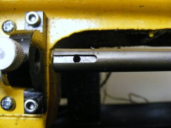
In this photo the knurled knob has been taken off the end of the rod and the rod withdrawn slightly to show the end of the rod. A 3 mm slot has been milled in the rod and a 3 mm hole drilled. Note the support block on the left of the photo. This has a knurled screw with a conical tip to the screw thread. When the rod is in the support block the screw runs in the groove and stops the bar from turning but it is free to slide. However, if the screw is tightened into the hole then the rod is rigidly fixed in a defined position. When the bar is rigidly fixed then the DRO can be used. When the rod is free to slide then it can be used in autostop mode to trigger the microswitch. In practice, the knurled knob on the end of the rod is adjusted with the bar rigidly fixed so that it is just on the point of triggering the microswitch. The datum for the DRO and the microswitch actuating are then the same.
The electrical circuit for the autostop is described in the subsection entitled Control Circuits.
The autostop circuit was later modified so that it would also control the main lathe motor (see lathe motor control). This enables the autostop to be used for screw cutting.
The autostop circuit was later modified so that it would also control the main lathe motor (see lathe motor control). This enables the autostop to be used for screw cutting.
