Ball turner Mk2
I made a ball turner many years ago primarily to make knobs for various modifications to the lathe. The original version swung around the lathe axis in the horizontal plane. The ball turner works very well but whenever I want to use it I have to remove the topslide in order to attach the ball turner.
The alternative configuration is the make a ball turner that swings about the lathe axis in the vertical plane. Many users have made a simple bracket/holder to mount a standard boring head onto the topslide. The boring head is horizontal and it swings the tool around the lathe axis in the vertical plane.
The boring head provides an easy way of moving the tool in order to set the radius of the ball to be turned. The advantage of this arrangement is that the ball turner becomes a simple addition to the topslide making it very quick and simple to set up.
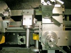
This photo shows my boring head lying on the lathe bed between the chuck and the cross slide. It can be seen that on the minilathe there is insufficient room to fit a boring head to the top post for ball turning. This is true even for my modified minilathe which has extended forward travel and an extended cross-slide.
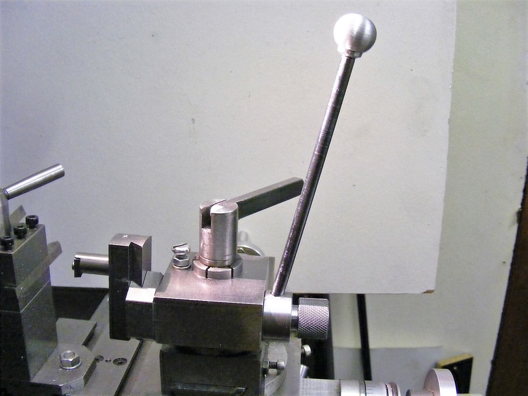
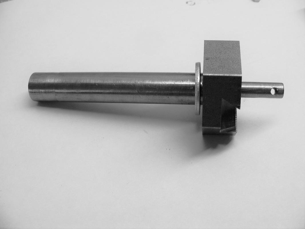
In order to make a simple toolpost mounted ball turner a shortened version of a boring head was needed. Balls in excess of 25 mm are rarely needed so I designed a simple accessory to facilitate this as shown in the header photograph.
|
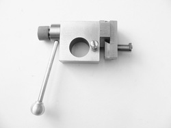
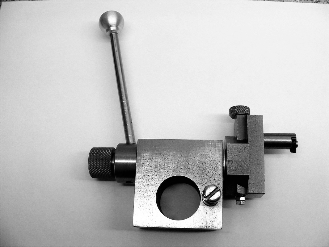
The ball turner consists of a block that can be mounted on the toolpost. The handle on the left rotates a shaft running through the toolpost block. On the right hand side the shaft connects to a hexagonal block that has a dovetail milled into the face. Another block, carrying the tool, with a matching dovetail slides in the hexagonal piece.
The knurled knob on the left hand side operates a screw that passes through the centre of the shaft and the pressure from this screw locks the two dovetails together |
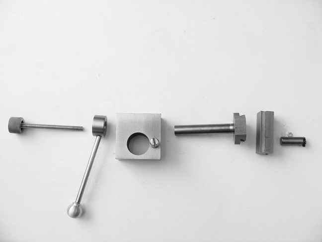
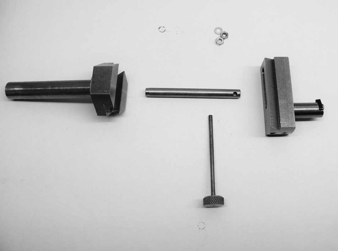
The photo above shows the component of the ball turner. From left to right these are:
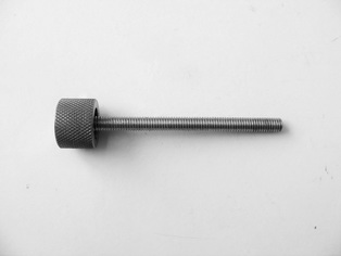
A locking screw
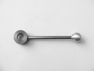
A collar with lever
A toolpost block
The rotating shaft with a dovetail on the right hand end
A dovetail block with the tool
A locking screw
A collar with lever
A toolpost block
The rotating shaft with a dovetail on the right hand end
A dovetail block with the tool
|
The tool was a short length of 10 mm steel with a TCMT carbide insert secured to one and as shown here.
The end of the 10 mm steel was milled leaving a small ledge to support the back of the insert. The carbide insert was then placed in position and stuck in place with cyanoacrylate adhesive. Using a 2.5 mm drill the position of the hole in the insert was spotted through to the steel. The tool was heated and the insert was removed. The screw hole was then drilled 2.1 mm and tapped M2.5 |
The the steel was then cleaned up with a file to remove any burrs and the insert fixed in place with an M2.5 screw. Note. The nut behind the tool is not part of the tool. It was used to prevent the the tool from rolling during photography.
The dovetail block carrying the tool is made from a piece of 16 x 19 mm steel. The dovetails were cut on the mill using a 60 degree dovetail cutter.
The hole for the cutter was not made until the final assembly stage of the ball turner.
The hole for the cutter was not made until the final assembly stage of the ball turner.
|
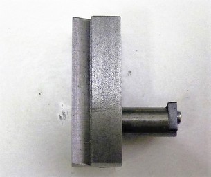
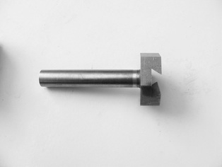
The rotating shaft is a length of 12 mm mild steel round stock and the dovetail was formed in a 12 mm length of 32mm hexagonal bar.
The shaft was drilled through 5 mm. The hole was opened out to 6 mm for most of its length leaving the last 12 mm at 5 mm diameter. The 5 mm end was tapped M6. The piece was lightly knurled at the threaded end and chamfered. Hexagonal bar was used for the dovetail block because it is much easier to hold in the miill vice than round stock. |
The first operation was to face a piece of 32 mm hex bar in the lathe and then drill out a hole 12 mm diameter to a depth of 13 mm. The end of the bar was then cut off at 13 mm from the faced end. This was mounted on parallels, good face down, in the mill vice and the end of the block faced with a milling cutter. A 12 mm wide groove was made down the centre of the block to a depth of 6 mm and then the dovetails were cut in the side of the groove. The dovetails were cut to closely match the dovetail in the toolholder block. The two parts should slide freely in each other.
After cutting the dovetails the block and the shaft were degreased in solvent. The hole in the block and the knurled end of the shaft were coated in high strength retainer and the two parts pressed together in the bench vice. The shaft must not protrude into the dovetail slot.
After cutting the dovetails the block and the shaft were degreased in solvent. The hole in the block and the knurled end of the shaft were coated in high strength retainer and the two parts pressed together in the bench vice. The shaft must not protrude into the dovetail slot.
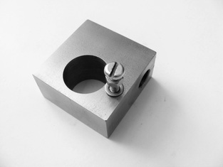
The toolpost block is just a piece of 25 x 50 x 50 mild steel cut off from a length of 25 x 50 mild steel bar. This was drilled and bored out 25 mm diameter through the thin dimension to fit on the toolpost.
It was then drill through and reamed 12 mm diameter in the other dimension as shown here.
The M5 vertical screw shown allows the height of the block on the toolpost to be adjusted.
It was then drill through and reamed 12 mm diameter in the other dimension as shown here.
The M5 vertical screw shown allows the height of the block on the toolpost to be adjusted.
|
The handle was made from a 90 mm length of 6 mm mild steel rod that was threaded M6 at both ends for a length of 5 mm.
The collar is 25 mm diameter and 12 mm thick. It was drillled out 12 mm to be a sliding fit on the shaft. The collar was cross drilled and tapped for an M5 grub screw that is used to lock it to the shaft. The collar was also cross drilled and tapped M6 at an angle of 15 degrees for the handle. The 16 mm ball was made using the ball turner. |
|
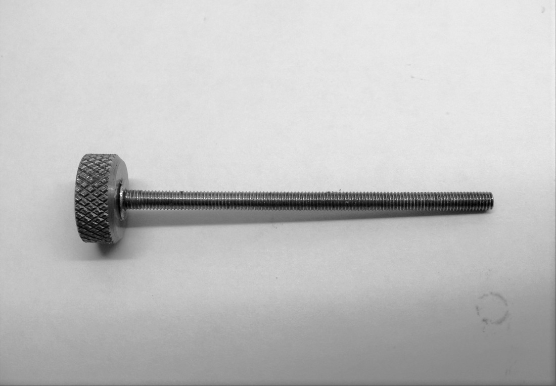
The locking screw is a length of M6 studding that runs through the shaft. The knurled knob was a short offcut of 19 mm steel bar that was faced and knurled in the lathe. It was bored out 5 mm and tapped M6. The knob was secured to the shaft using high strength retainer.
|
The tool was assembled and fixed to the lathe toolpost with the dovetail block horizontall. The height was adjusted so that the centre of the dovetail block was lined up with the lathe spindle axis. The dovetail block was slid in the direction of the chuck and locked in position using the locking screw so that it is fully engaged with the dovetail in the hexagonal block. The hole for the tool was then drilled in the dovetail block using a 10 mm drill in the lathe chuck.
The final operation was to use the ball turner to make the 16 mm knob for the handle. A piece of 19 mm aluminium bar 19 mm long was cut. It was drill 5 mm in the lathe about 10 mm deep and tapped M6. This was screwed to a piece of M6 studding that was gripped in the lathe chuck. The ball turner was centred in the middle of the aluminium and set at a radius to just clip the edges of the aluminium as the handle was swung round. This was repeated reducing the radius each time until the ball was formed. The ball was then removed from the studding and screwed onto the end of the handle.
This tool is not better than my other ball turner but it is much quicker to put it into operation. No dismantling of the topslide is required since it just slips onto the toolpost.
Some improvements.
The ball turner described above works fine although it is a little tricky to adjust the feed between cuts. After completing it I realised that there is a relatively simple way to provide a feed screw to adjust the depth of cut. The ball turner has been modded to include this feature.
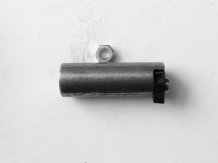
This photo shows the modifications. on the left hand side is the base dovetail attached to the pivot rod. This was dismantled and reassembled so that the threaded end of the pivot rod was at the far end of the rod rather than at the dove tail end. The push rod shown in the centre slides in the bore of the pivot rod. When pushed right in then the rod is flush with or slightly below the bottom of the dovetail. The sliding dovetail on the right has been modified with a groove in the bottom of the dovetail section. The push rod fits into this groove. The feed screw is shown at the bottom and this engages in the small tapped hole in the end of the push rod.
|
This shows the 6 mm push rod slid into the pivot rod.
|
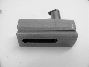
The centre of the sliding dovetail is milled out to form a slot 6 mm wide and 6 mm deep to accommodate the end of the push rod as shown.
The parts are assembled by pushing the push rod into the pivot rod. The head is then slid into the dovetail. An M6 screw is then screwed into the end of the pivot rod pushing the push rod up into the groove of the sliding head. The head is push over so that the cutter is in the centre and the screw tightened. This locks the head in this position. A 2.5 mm hole is then drilled through the end of the sliding head and through the push rod. The unit was then dis-assembled and the hole in the push rod tapped M3. The hole in the end of the sliding unit was enlarged to 3.5 mm. A similar 3.5 mm hole was drilled at the opposite end of the slot.
|
The lead screw was made by knurling some M12 round stock and drilling it out 2.5 mm. A 6 mm slice was the screwed onto the end of some M3 studding and secured using high strength Loctite retainer.
|
The unit was now assembled. The push rod was dropped into the pivot rod and the sliding dovetail slipped into place. The push rod was pushed up with a screw in the threaded portion of the pivot rod. The hole in the push rod was aligned with the hole in the end of the slider using a small screwdriver. The feed screw was screwed through the hole into the push rod until it emerges from the hole on the other side of the slider. Two M3 nuts were screwed onto the protruding feed screw and then locked together. Turning the knurled knob now causes the slider to to move back and forth in the dovetail.
The rotating head can now be fitted into the tool post block and the collar and handle attached
The original knurled locking screw that went through the pivot rod was shortened and screwed into place.
