Bandsaw stand
The 6 x 4 bandsaw seems to be used by many hobby engineers. It is a sturdy, robust machine and the main problem reported on the Yahoo 6x 4 bandsaw Group seems to be the stand. Many dislike the stand because it is too flimsy. I have not found this a problem at all. Provide the bolts are done up tight then the stand seems to be quite rigid.
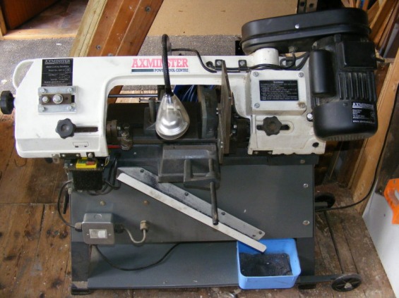
My main dislike about the basic stand is more to do with controlling the swarf. This gets everywhere and within a short space of time the shelf becomes covered with it. The header photo shows some of the changes I have made to get round this. Firstly, a plywood panel has been added to the cutting side of the machine to stop swarf falling onto the shelf. This keeps the shelf clean but just means more ends up on the floor. To control this I have added an inclined gutter that directs the swarf to a small plastic container. The gutter was made by slitting some square PVC rainwater down pipe down the middle using a circular saw. This is the screwed to the plywood panel, as shown.
My second dislike is that when the saw arm is in the vertical position any attempt to move the saw by lifting the front and dragging it on the wheels can lead to the whole saw tipping backwards. ( I know the saw is better moved with the arm lowered but sometimes you just don't think). The problem arises because the arm is so heavy and the wheels are so close to the stand that the centre of gravity is behind the wheels if the front of the saw is lifted by more than about 10-15 mm. To overcome this I moved the wheels about 100 mm behind the stand. To do this two 25 x 25 x 3 mm steel angle pieces were attached to the stand close to the floor and these extend behind the stand. The wheels then run on an axle between the two pieces of angle, as shown in the header photo.
Having added the steel angle pieces along both sides of the stand it was a simple job to add another shelf below the existing shelf, thereby increasing the storage space and this also provides a place to stand the collection vessel at the end of the gutter.
Also shown in the header photo is a lamp that was added. This was attached directly to the swinging arm and it has a flexible neck so that light can be directed to either side of the saw blade. The lamp is a low voltage halogen lamp. The switch for the light is mounted on the plywood panel beneath the stop/start buttons.
Standing up directly to the right of the lamp is a new saw table to replace the flimsy version supplied with the lathe. This will be described on a separate page.
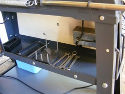
This shows the other side of the bandsaw. The middle shelf has been inverted and the edges stiffened with 25 x 25 x 3 mm steel angle. Used in this way it forms a tray so that tools do not fall off the edge. The tray is very useful for storing bandsaw accessories. On the tray is a clamp for holding short workpieces and a fence for the saw table. Both of these accessories will be described on other pages. The galvanised box fixed to the plywood panel houses the back of the light switch and the transformer for the light.
