Determining gear pressure angle.
I needed to measure the pressure angle of some existing gears, so I could make a new one to mesh with them. My particular need was to make a new MOD 1 change gear for my lathe, but the method set out here could be used to establish the pressure angle of any gear large enough to be photographed clearly.
To design a gear cutter it is necessary to know the pressure angle. There does not seem to be any information from the manufacturers, suppliers or the internet about the pressure angle of the change gears for the minilathe. There is also little information that I can find on how to determine the pressure angle of gears using the limited equipment available to the amateur engineer.
In order to determine the pressure angle I decided to try to use Ivan Law's circular approximation to the involute curve (see Ivan Law's book "Gears and Gear Cutting"). Since only two pressure angles are in common use, 14.5 and 20 degree, it is only necessary to decide which best fits the gear profile.
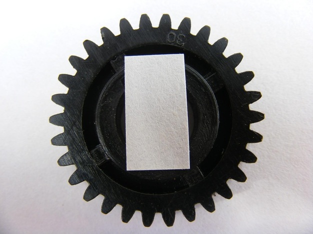
The first step was to take a sharply focussed photograph of the gear as shown in the header photo. This photo was taken of the 30 tooth change gear using the super macro facility on my Fuji Finepix S5800 camera. Note the piece of paper laid over the central hole. This was used to provide a focussing object for the camera (other wise it would have focussed on the bottom of the central hole and the gear surface would have been out of focus). The image was then transferred to a CAD worksheet.
To design a gear cutter it is necessary to know the pressure angle. There does not seem to be any information from the manufacturers, suppliers or the internet about the pressure angle of the change gears for the minilathe. There is also little information that I can find on how to determine the pressure angle of gears using the limited equipment available to the amateur engineer.
In order to determine the pressure angle I decided to try to use Ivan Law's circular approximation to the involute curve (see Ivan Law's book "Gears and Gear Cutting"). Since only two pressure angles are in common use, 14.5 and 20 degree, it is only necessary to decide which best fits the gear profile.
The first step was to take a sharply focussed photograph of the gear as shown in the header photo. This photo was taken of the 30 tooth change gear using the super macro facility on my Fuji Finepix S5800 camera. Note the piece of paper laid over the central hole. This was used to provide a focussing object for the camera (other wise it would have focussed on the bottom of the central hole and the gear surface would have been out of focus). The image was then transferred to a CAD worksheet.
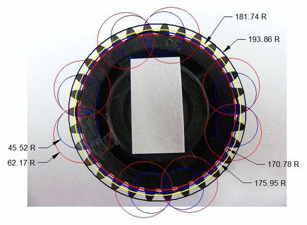
The above photo is the gear taken from the CAD worksheet. The CAD program used was DeltaCad. This has a function to make a circle by inputting any three points on the circumference. Using this function three equally spaced points (i.e. every tenth tooth) were choosen on the tips of the gear teeth to form a circle that circumscribes the complete gear. This is the outer black circle. This has a radius of 193.86 mm and we will call this R. The gear is a MOD 1 gear and the actual radius is 32 mm and the difference arises because of the photo magnification. However, this difference does not affect subsequent calculations. Next the pitch circle was drawn. This has a radius of N x R/(N+2) = 181.74, where N is the number of teeth, and is shown on the drawing by the yellow circle. The base circles are then drawn for both the 14.5 degree pressure angle and the 20 degree pressure angle. The large blue circle is the base circle for 14.5 degree pressure angle and it has a radius of N x R x Cos(14.5)/(N+2) =175.95 and the large red circle has a radius N x R x Cos(20)/(N+2) =170.78.
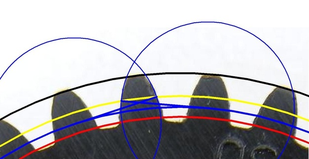
The photo above is a greatly enlarged view of the gear teeth. A blue line has been drawn from the pitch point, where the pitch circle intercepts the gear tooth, at a tangent to the 14.5 degree base circle. This has been done on both sides of the tooth. From the end of the tangent lines circles have been drawn that intercept the two pitch points. The fit of these two circles to the profile of the tooth is not good. The real tooth is narrower at the tip and wider at the base than that defined by the two circles.
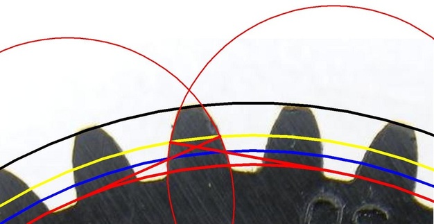
This is a similar photo to the previous one but this time lines have been drawn from the pitch point at a tangent to the 20 degree base circle. The circles centred on the tangent ends now very closely match the tooth profile
These comparisons have been made on four different teeth on the gear and every time the construction based on a 20 degree pressure angle gives an almost exact fit to the tooth profile whereas that based on the 14.5 degree profile gives a bad fit at the tooth tip and base.
On the basis of these results it is clear that the pressure angle of the gear is 20 degrees.
Acknowledgement.
My thanks are due to Dick Mason who advised me of an error in the original version of this page. This has been corrected
