Coolant pump system.
Normally, when using the lathe, I use a brush to apply coolant/lubricant to the workpiece. This works fine for most jobs involving straightforward turning operations. However, for some operations such as screw cutting, it seems that a third hand is required to apply the coolant because the other two are fully occupied. It is also easy to forget to apply lubricant when carrying out complex operations.
I did look into the possibility of buying a coolant system but all the commercial units seem really over the top for use on a minilathe. They were large requiring several litres of coolant to fill and the flowrates were measured in litres per minute whereas the coolant requirement on the minilathe was more of the order of 10 ml per minute.
I then started to investigate if I could make a simple and cost effective unit. The design criteria were as follows:
1. The unit should be small and compact - I only have a small workshop
2. It should be easily dismountable from the lathe when it is not required.
3. The amount of coolant in the system should be small, not more than 500 ml.
4. The flow rate of coolant should be variable within the range 0 - 100 ml/minute i.e. from a drip to a fine jet
5. It should be safe. This means a low voltage pump and fully enclosed motor.
6. Components should be cheap and readily available.
I could easily envisage the type of system required. A small reservoir with a large catchment tray would be placed under the lathe. Coolant from the reservoir would be pumped up to a nozzle located directly over the cutting tool. Excess coolant then collects in the tray and drains back into the reservoir. This all sounds very simple but the sticking point for many months was what to use as a pump. The answer was staring me in the face evey time I drove the car. The windscreen washer has a small compact low voltage pump capable of sending out a considerable jet of liquid. The only real questions I had were would a windscreen washer pump be compatible with mineral oil based coolants and how reliable would it be if run continuously.
In one of my junk boxes I had a couple of old windscreen washer pumps. Both had seen some previous service. I partially dismantled them and discovered that one was a rubber impellor type pump and the other was gear pump. I discounted the first pump on the grounds that the rubber impellor was probably not going to be good in contact with the oil based coolant. The second pump had plastic gears, probably acetal, and I decided to test this pump for application as a coolant pump. The first tests were made using water and at the rated voltage the flow was several litres per minute. After running a few minutes the motor was quite warm. This was hardly surprising since windscreen washers are designed for intermittant use. On reducing the voltage the pump flow decreased and at 2 volts is was still delivering over 100ml/min. At this voltage the pump would run for hours and not get hot. It was also virtually silent. I then changed the pumped fluid to a mixture of 50% white spirit and 50% motor oil and set the pump working a 2 volts for several hours. At the end of that period I dismantled the pump again and examined the gears and seals for any sign of damage. None was evident so I decided that the pump could form the basis for my coolant system.
In order to fit the catchment tray under the lathe it must be raised up to provide clearance. I had already done this as part of another modification, see here.
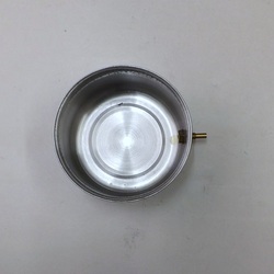
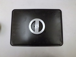
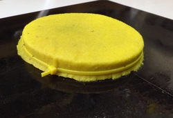
This shows the coolant reservoir. It is a small stainless steel dish 90mm diameter and 45 mm high designed as a food container. It holds about 250 ml of coolant. A 6mm hole was drilled near the bottom. A 25mm M6 brass hexagon bolt was drilled out 3 mm and the threads turned away for about 13 mm. This bolt was passed through the hole using a fibre washer as a seal and tightened against the side of the dish with an M6 nut.
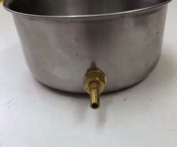
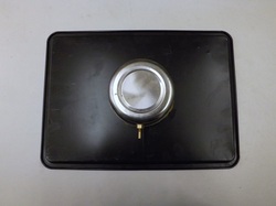
This is a close up of the outlet connection on the reservoir.

The collection tray is a tin baking tray 320 x 230 x 13 mm. This was drilled in the centre and also at four points around the centre hole as shown.
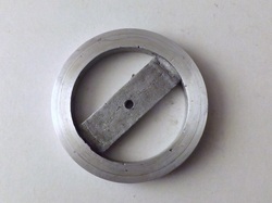
Under the tray is bolted a round aluminium disc that fits into the top of the reservoir. The disc is 12mm thick but the central web is 6 mm below the top surface of the disc. When the disc is bolted to the underside of the tray the centre of the tray is pulled down creating a shallow depression into which the coolant collects and flows into the reservoir.
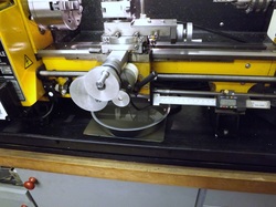
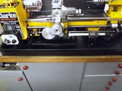
The disc was an aluminium casting that was then machined on both faces and the perimeter.
The disc was an aluminium casting that was then machined on both faces and the perimeter.
The centre hole in the disc is tapped M6 and it is attached to the tray with an M6 screw.
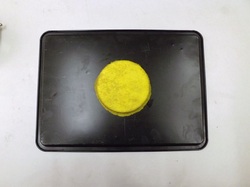
The disc is covered by a piece of filter cloth. This is a piece of non-woven household cleaning cloth.
The reservoir fits snugly over the filter cloth and holds it in place. In use this assembly is turned over so that the reservoir is under the tray.
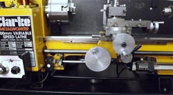
This shows the catchment tray in position under the lathe bed with the reservoir underneath.
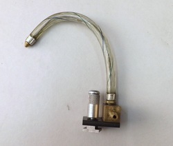
The nozzle assembly consist of a short length of 12 mm square brass drilled out to accept a short lenght of 5mm OD brass tube for the coolant feed. It is cross drilled half way through and tapped M5 for the plastic nozzle. This nozzle was supplied as the flexible spout for an oilcan. (Another rigid nozzle was also supplied and used with the oilcan). The flexible pipe has a length of stiff wire inside permitting the flexible tube to be bent into any position.
The brass block is attached to a short length of 4mm steel strip using M3 countersunk screws. The steel strip is also drilled for a knurled thumb screw that screws into a tee nut.
The brass block is attached to a short length of 4mm steel strip using M3 countersunk screws. The steel strip is also drilled for a knurled thumb screw that screws into a tee nut.
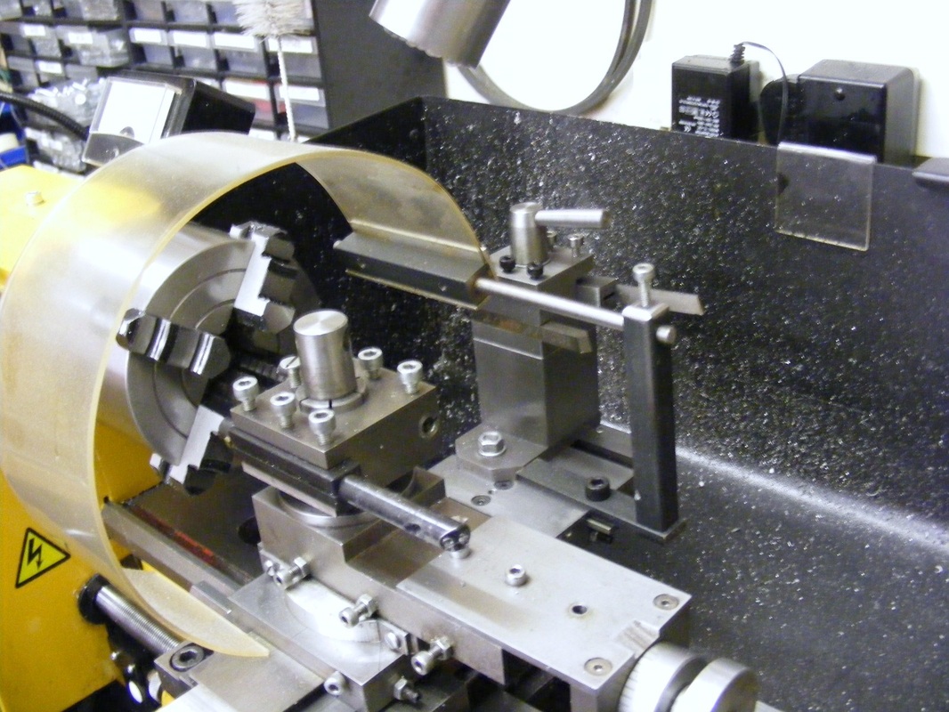
The nozzle assembly clamps to the tee slot cross slide with the tip directly over the cutting tool.
An alternative to using a tee nut to clamp the nozzle is to fix a small, powerful, neodymium magnet to the brass block. This enables the nozzle to be fixed to either the cross sliide or the top slide. The only down side to this arrangement is that the magnet tends to attract much swarf when machining steel.
An alternative to using a tee nut to clamp the nozzle is to fix a small, powerful, neodymium magnet to the brass block. This enables the nozzle to be fixed to either the cross sliide or the top slide. The only down side to this arrangement is that the magnet tends to attract much swarf when machining steel.
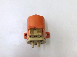
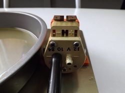
The pump is shown in this photo. It is marked SEIM and made in France.
The reservoir is connected to the pump inlet and the outlet is connected to the nozzle. Originally clear flexible PVC tube was used for the fluid lines. However, on prolonged contact with mineral oil these became hard and stiff. They have been replaced by nitrile rubber tubes, as used for diesel fluel lines, which are much more oil resistant. Their are two spade connectors on the top of the pump for the electrical supply.
The reservoir is connected to the pump inlet and the outlet is connected to the nozzle. Originally clear flexible PVC tube was used for the fluid lines. However, on prolonged contact with mineral oil these became hard and stiff. They have been replaced by nitrile rubber tubes, as used for diesel fluel lines, which are much more oil resistant. Their are two spade connectors on the top of the pump for the electrical supply.
The electrics.
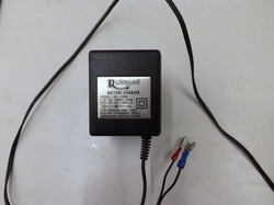
The pump is connected to a dc plug in transformer (wall wart in US). This is rated at 9V and 500 ma which is more than enough for the pump. The plug in transformer is connected to a lamp dimmer to provide a variable pump feed. The electrical schematic is shown below.
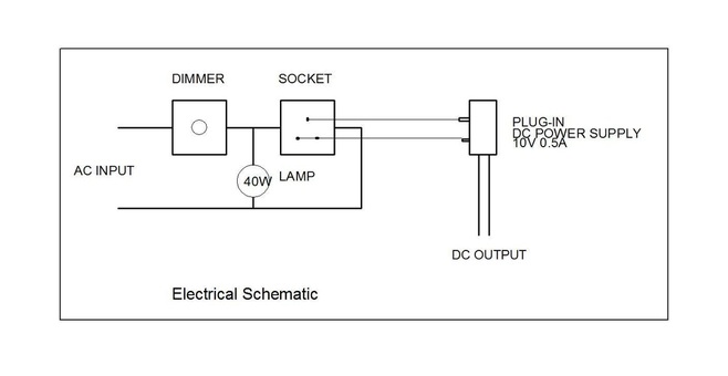
The 40W lamp is included in the circuit to load the dimmer. The pump itself only draws less than 1 watt and lamp dimmers require a minimum load (usually 40 watt) to function correctly. With this arrangement the pump speed can be varied to provide anything fromm a slow drip to a jet of coolant.
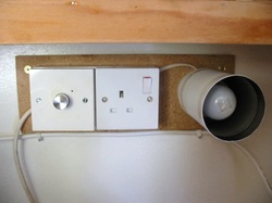
In practice the dimmer, socket and lamp are mounted on a small board above the lathe. This variable power socket can also be used to provide variable power to other equipment if needed within the power limitations of the dimmer (250 Watt)
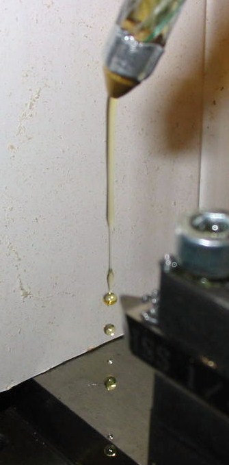
This pumped coolant system works very well and it comes into its own when doing complex lathe operations where insufficient hands are available or where concentration on the machining may lead to neglect of cooling and lubrication. The big problem with using the system at high flowrates is that the coolant tends to spray everywhere especially if working close to the chuck.
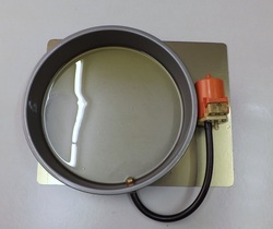
Spray sheild.
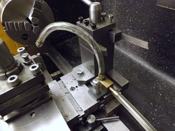
To minimise the spray problem a Perspex (Plexiglas in the US) spray shield was constructed, see above. The shield clamps to the cross-slide so that once positioned over the tool it will move with it. The sheil was made by heating a strip of 80 x 370 x 2.5 mm Perspex in a domestic oven until it goes floppy. It was fully supported during the heating process on a strip of 1/8" fibreboard. When floppy it was removed and wrapped around a paint tin (diameter circa 130 mm) to form the curved shape. The curved strip was screwed to a piece of 12 mm square steel using a piece of 13 mm aluminium ange to spread the stress around the screws . The 12 mm square steel was drilled through 6 mm diameter and a rod fixed in position using Loctite. A simple bracket was made to attach this to the cross slide.
A note on coolants.
I have used water based coolants (soluble oil, suds) on the lathe but I find this leads to slight surface corrosion of the ways unless the lathe is cleaned well after use. For this reason I prefer to use oil based coolants. I generally use a mixture of SAE30 motor oil diluted 50/50 with white spirit. This I find works well for aluminium and steel.
A few improvements.
The coolant system as described above works well. The only real problem is that slipping the unit under the lathe is a messy business because there was always a spillage of oil. To overcome this a few changes were made.
A shallower tray was used as a reservoir. This was a 200mm diameter sponge tin. The tin is circa 30 mm high and this enables it to slip easily under the lathe. The tin was cemented to a piece of sheet steel 200 x 250 mm, using silicone sealant, and the pump was mounted on the sheet.
The pump was mounted on the sheet using two M3 countersunk screws. The sheet was punched to provide recesses for the screw heads so that it would lie flat under the lathe
The same collection tray was used as previously. The filter cloth was held onto the disc using cable ties as shown here.
The new reservoir fits easily under the lathe. When not in use it can be removed at the back of the lathe and just sits on a narrow shelf behind the lathe at the same height as the top of the drip tray.
The collection tray just sits on top of the reservoir. It can be remove from the front of the lathe. When not in use the collection tray sits at the back of the lathe on top of the reservoir.
These small modifications mean that it is simple to stow the coolant system behind the lathe when not in use. After use the coolant is simple pumped out into a bottle, the collection tray removed and the reservoir lifted onto the shelf at the back of the lathe. Practically no coolant is spilt during this process.
One other small improvement was to change the power supply from a 9 volt unit to a 3 volt 1 amp unit. This gives more precise flow regulation.
One other small improvement was to change the power supply from a 9 volt unit to a 3 volt 1 amp unit. This gives more precise flow regulation.
