Cross slide motor
Many up market lathes have a drive connected to the cross slide. Usually the drive is taken from the leadscrew. A cross slide drive permits the cross slide to be driven forward at a slow steady rate for finishing facing cuts.
I have added a small dc motor to the cross slide to provide a good constant feed. The motor used is more or less identical to the motor used to drive the leadscrew except it is a 12 V 30 rpm unit. The drive from the motor can be engaged or disengaged simply by pulling the handle in and out.
I have added a small dc motor to the cross slide to provide a good constant feed. The motor used is more or less identical to the motor used to drive the leadscrew except it is a 12 V 30 rpm unit. The drive from the motor can be engaged or disengaged simply by pulling the handle in and out.
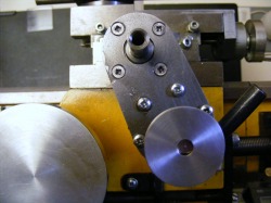
A bracket was made from 1/8" steel plate that mounts the motor to the cross slide directly behind the graduated collar. This is secured with four countersunk M3 screws. If the motor were mounted directly below the feedscrew, it would hinder access to the carriage handwheel, so the mounting bracket is angled about 25 degrees to the right as shown here. This still allows ample access to the half-nut lever.The pulley at the bottom is machined from 1.1/2" aluminium and it is attached to the motor shaft with a grub screw. It has a 60 degree vee groove milled in the periphery. Around the cross slide shaft can be seen a thick washer that compensates for the thickness of the bracket. The graduated collar fits onto the cross slide shaft as normal.
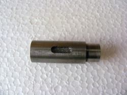
This shaft butts onto the end of the cross slide shaft. It is drilled out to 6 mm and is held on to the cross slide shaft by an M6 screw that passes through the shaft and screws into the end of the cross slide shaft. The main diameter of the shaft is 12 mm but the end is turned down to 10 mm diameter for a distance of 6 mm. This turned down section is for the cross slide drive pulley which turns freely on the end of the shaft. Notice the milled out slot in the drive shaft.
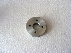
This photo shows the cross slide pulley. It is 30 mm diameter and machined from aluminium. It has a 60 degree vee groove around the periphery. Notice the four holes in the pulley. These holes accept the drive pin on the handwheel.
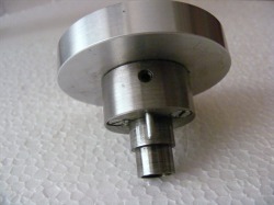
This shows the cross slide handle with the shaft inserted. The small grub screw visible locates in the milled groove on the shaft. This screw is only tightened sufficiently to prevent the shaft being pulled out of the handle. The shaft should be able to slide in and out of the handle to the extent defined by the length of the milled groove in the shaft. The cross slide pulley fits onto the narrow part of the shaft but it can rotate freely on the shaft. Notice the pin protruding from the boss of the handle. This pin can locate in any of the four holes in the pulley.
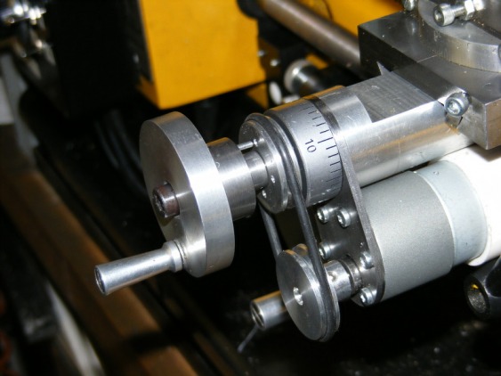
The header photo shows the unit assembled onto the cross slide shaft. The 6 mm screw that clamps the assembly to the cross slide shaft can be seen in the middle of the handle. The pin is not located in the pulley hole and, because the shaft can rotate freely without turning the pulley, then the handle can be turned normally to move the cross slide. This can be done whether the motor is running or not.
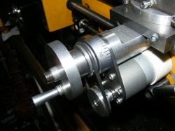
This shows the cross slide motor engaged to drive the cross slide. The handle has been pushed in so that the pin enters one of the holes in the cross slide pulley. Now drive from the motor is transmitted to the handle and it will rotate driving the cross slide. At any time the handle can be pulled out to immediately disconnect the drive. In this photo also notice the white sleeve around the motor that presses hard against the apron. This is a piece of 1.1/4" polypropylene waste pipe that has been slit so that it will fit around the motor. The motor leads pass through the open slit at the bottom. This piece of pipe protects the motor terminals from swarf.
The electric circuit for controlling the motor are given in the sub section entitled Control circuits
