Designing gear cutters
Making gears requires making a cutter with the appropriate profile. The amateur machinist usually does this using the button method developed by Ivan Law and further improved by John Stevenson. They have both given tables for the button diameter, button spacing and infeed required to produce the cutter. This method relies on the fact that the involute curve can be closely approximated to a circle over the limited distance of a gear tooth.
I can find relatively little information on the methods used to create the tables of button diameter, button spacing and infeed for the button method and on this page I have developed generalised equations for these parameters based on the geometry. With these equations it is straightforward to design cutters for any gear given the number of teeth, the module and the pressure angle.
I can find relatively little information on the methods used to create the tables of button diameter, button spacing and infeed for the button method and on this page I have developed generalised equations for these parameters based on the geometry. With these equations it is straightforward to design cutters for any gear given the number of teeth, the module and the pressure angle.
Some definitions
Number of teeth (N). This is simply the number of teeth on the gear.
Pitch circle diameter (pcd). This is the diameter of an imaginary circle running through the gear teeth that is used to calculate the tooth profile.
Module (M). This is the pitch circle diameter divided by the number of teeth. Thus pcd = NM.
Crest circle diameter (ccd). This is the circle that touches the extremities of all the teeth. This is the outside diameter of the disc from which the gear is made. The ccd = (N+2)M
The root circle diameter (rcd). This is the circle that touches the base of all the teeth. The rcd is equal to the ccd minus twice the full depth of the teeth(D) + clearance (f). The full depth of the tooth + clearance is usually expressed as D+f and this is the depth the gear cutter must be fed into the gear blank when cutting the teeth. By convention D+f = 0.6866 x circular pitch = 0.6866 (PI) NM/N =2.157M. Thus the root circle diameter = (N+2)M - 4.314M = (N-2.314)M
The base circle diameter (bcd). This is the circle that is used to generate the involute profile of the teeth.
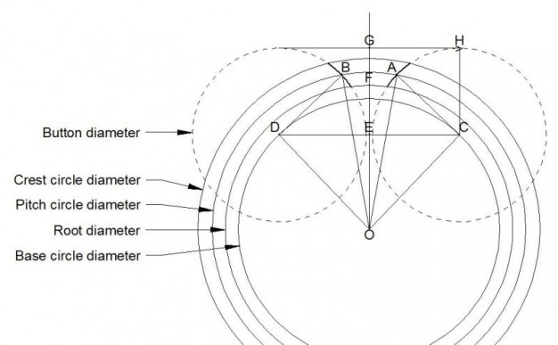
Pressure angle (p). This is the angle AOC in the diagram above. A line drawn from the intercept of the gear tooth with the pitch circle forms a tangent to the base circle at the pressure angle.
Angular pitch. (ap). This is the angle between any point on one tooth to a similar point on the next tooth.It is given by 360/N in degrees or 2(PI)/N in radians where PI = 3.142. The angle BOA in the diagram above is equal to 1/2 the circular pitch.
Button diameter (bd). This is the diameter of the button used to form the cutter. The button radius AC extends from the pitch point A on the tooth to a tangent C on the base circle.
Pitch circle diameter (pcd). This is the diameter of an imaginary circle running through the gear teeth that is used to calculate the tooth profile.
Module (M). This is the pitch circle diameter divided by the number of teeth. Thus pcd = NM.
Crest circle diameter (ccd). This is the circle that touches the extremities of all the teeth. This is the outside diameter of the disc from which the gear is made. The ccd = (N+2)M
The root circle diameter (rcd). This is the circle that touches the base of all the teeth. The rcd is equal to the ccd minus twice the full depth of the teeth(D) + clearance (f). The full depth of the tooth + clearance is usually expressed as D+f and this is the depth the gear cutter must be fed into the gear blank when cutting the teeth. By convention D+f = 0.6866 x circular pitch = 0.6866 (PI) NM/N =2.157M. Thus the root circle diameter = (N+2)M - 4.314M = (N-2.314)M
The base circle diameter (bcd). This is the circle that is used to generate the involute profile of the teeth.
Pressure angle (p). This is the angle AOC in the diagram above. A line drawn from the intercept of the gear tooth with the pitch circle forms a tangent to the base circle at the pressure angle.
Angular pitch. (ap). This is the angle between any point on one tooth to a similar point on the next tooth.It is given by 360/N in degrees or 2(PI)/N in radians where PI = 3.142. The angle BOA in the diagram above is equal to 1/2 the circular pitch.
Button diameter (bd). This is the diameter of the button used to form the cutter. The button radius AC extends from the pitch point A on the tooth to a tangent C on the base circle.
Geometry
In the diagram the line AC is a tangent to the base circle and it is thus at right angles to the radius OC.
Calculation of the base circle diameter.
OC = AO Cos p
but OC = 1/2 bcd and AO = 1/2 pcd
Thus
bcd = pcd Cos p
bcd = NM Cos p
Calculation of the button diameter.
AC = AO Sin p
but AC = 1/2 bd and AO = 1/2 pcd
Thus
bd = pcd Sin p
bd = NM Sin p
Calculation of the button separation.
The triangle CEO is a right angled triangle.
Hence:
CE = CO Sin (angle COE)
CE = CO Sin (angle AOC + angle AOG)
CE = CO Sin (p + ap/4)
CE = CO Sin (p +360/4N)
CE = CO Sin (p + 90/N)
But CE = 1/2 the button separation and CO = 1/2 bcd
Hence:
The button separation bs = bcd Sin (p + 90/N)
but bcd = NM Cos p
Thus
bs = NM (Cos p){Sin (p + 90/N)}
Calculation of infeed.
I measure infeed from the outer edge of the buttons ie. point G.
The infeed (inf) is the distace GF ie from point G to the root circle.
GF = CH - EF = CH - (FO - EO)
CH = 1/2 button diameter
FO = 1/2 root circle diameter
EO = 1/2 bcd Cos (p + 90/N)
but bcd = pcd Cos p
Hence
EO = 1/2 NM (Cos p){ Cos (p + 90/N)}
Hence:
inf = 1/2 button diameter - 1/2 root circle diameter + 1/2 NM (Cos p) {Cos (p+90/N)}
inf = 1/2[ NM Sin p - (N-2.314)M + NM (Cos p){Cos (p + 90/N)}]
inf = 1/2 M[ N Sin p - (N-2.314) + N (Cos p){Cos (p + 90/N)}]
Summary
There are thus three equations for expressing the button diameter (bd), button spacing (bs) and infeed (if) in terms of the number of teeth (N), the module (M) and the pressure angle (p)
bd = NM Sin p
bs = NM (Cos p){ Sin (p + 90/N)}
inf = 1/2 M[ N Sin p - (N-2.314) + N (Cos p){Cos (p + 90/N)}]
bd = NM Sin p
bs = NM (Cos p){ Sin (p + 90/N)}
inf = 1/2 M[ N Sin p - (N-2.314) + N (Cos p){Cos (p + 90/N)}]
Results
Some typical results for pressure angles of 20 degree and 14.5 degrees are shown below.
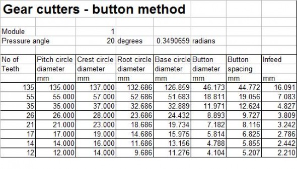
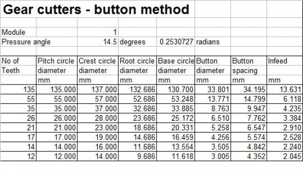
Note: Cutters for gears are normally produced in eight different sizes. These sizes cover the range from a 12 tooth gear to a rack. The cutters listed in the tables above cover this range. Thus the 12 tooth cutter covers the range 12-13 teeth, the 14 tooth cutter covers the range 14 - 16 teeth, the 17 tooth cutter covers the range 17-20 teeth, the 21 tooth cutter covers the range 21 - 25 teeth, the 26 tooth cutter covers the range 26 - 34 teeth, the 35 tooth cutter covers the range 35 - 54 teeth, the 55 tooth cutter covers the range 55 - 134 teeth and the 135 cutter covers the range 135 teeth to a rack.
The calculations are simply carried out using a spreadsheet as shown in the table above. Any values of number of teeth, module and pressure angles can be input.
A copy of the spreadsheet can be obtained, on request, using the contact form on the home page
The calculations are simply carried out using a spreadsheet as shown in the table above. Any values of number of teeth, module and pressure angles can be input.
A copy of the spreadsheet can be obtained, on request, using the contact form on the home page
Note added 30 October 2015
My thanks to Damian Poirier for pointing out a small error on this page which has now been corrected. The error does not affect the calculation or the results above.
My thanks to Damian Poirier for pointing out a small error on this page which has now been corrected. The error does not affect the calculation or the results above.
