Drilling machine improvement.
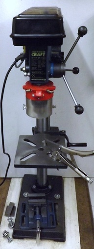
My drilling machine is a cheap unit from ALDI. Although cheap this drilling machine has quite a good specification and it includes a rack and pinion mechanism for raising and lowering the table. It has served me well for a number of years and my only real complaint has been that the maximum chuck to table distance is rather limited at around 170 mm. Whilst this sounds quite good, once you put a large 13 mm drill into the chuck that protrudes 120 mm, there is not much room left for the workpiece. On several occasions I have been forrced to drill freehand holes using a portable drill because I could not physically fit the item onto the drilling machine.
I did contemplate buying a new machine with a greater minimum chuck to table distance. However, most of the affordable options did not have very slow speed for drilling large holes and they lacked features such as the rack and pinion table lift. I decided to try and increase the height of the existing drilling machine by about 150 mm.
The existing machine has a pillar diameter of 46 mm and my first thought was to simply buy a length of 46mm steel tube and replace the existing pillar with something longer. I searched all the usual sources for steel tubing (including ebay) for 46 mm tube and it does not appear to be a standard size. The closest tube available was 1.3/4" which is 44.45 mm. Then I remembered that I had an old drill press and I checked the diameter of the column on this and it was the required 46 mm. I decided to try and attach a 150 mm piece cut from the old drill press onto the ALDI drill press.
It was straight forward to cut off a piece of pillar 150 mm long from the old machine. This was mounted on the lathe chuck and using my large diameter steady rest the ends were turned square.
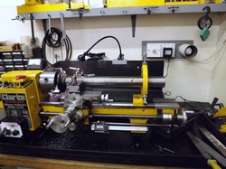
The pillar was removed from the aldi machine and it was found that the end of the pillar had been chamfered and it was not very square. In order to true up the end the pillar was mounted in the lathe as shown. The end was then trued up using a large coarse file with the pillar rotating slowly.
A piece of 1.5/8" tubing was a close fit in both the 150 mm extension piece and in the aldi drilling machine pillar. A 125 mm piece of this 1.5/8" tube was cut off. The pillar and the extension piece would be joined together using epoxy resin and the 1.5/8 tube to reinforce the joint.
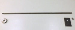
To ensure that both the pillar and the extension piece were aligned a 10mm rod was made to pass through the pillar. Both ends of the rod were threaded M10. One end screws into a stepped closing cap. A 6 mm thick oblong washer was cut and drilled for the other end of the rod
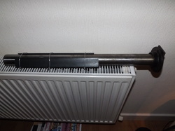
Firstly the pillar the extension and the reinforcement tubes were thoroughly cleaned using first caustic soda and then water. After drying the inside of the pillar and the extension were coated with plenty of epoxy resin as was the outside of the reinforcing tube. The parts were then slid together ensuring that the reinforcing tube was positioned centrally at the junction of the two pillar sections. The closing cap and rod were then passed through the assembly and the washer and nut loosely tightened at the flanged end. At the junction of the two pillar sections two pieces of 40 mm steel angle were strapped around the joint using stout wire to ensure that the tubes were aligned. The nut on the end of the through rod was then tightened down hard and the assembly left on a radiator for 10 hours to cure the epoxy resin..
This shows the top of the pillar. The closure is 10mm thick. The top flange is 46 mm diameter and 3 mm thick and the insert part of the closure is 41 mm diameter.
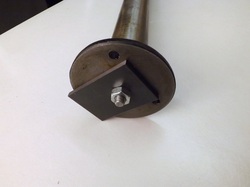
The other end of the pillar has the washer and nut.
Once the epoxy resin has set the two pieces of angle iron were removed and the through rod was undone and removed. The pillar was then mounted on the lathe as shown in an earlier photo and the whole pillar cleaned up using oil and emery cloth. The region around the join was cleaned especially well to remove any resin on the outside of the pillar.
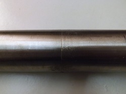
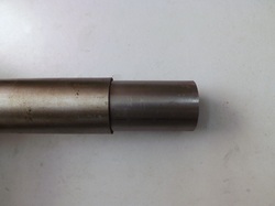
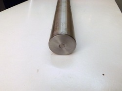
The two pillar sections are well aligned and the join is barely visible.
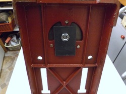
The pillar was then bolted to the base of the drilling machine. This photo shows the underside of the base. The endcap, through rod, washer and nut were then passed through the whole assembly and the nut tightened.
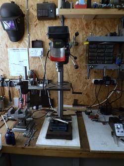
The table and drilling head were then fitted to the column. The new extended column provides more than 300 mm space from chuck to table. The increased column height also brings the work to a more comfortable working position.
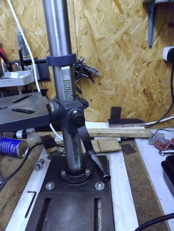
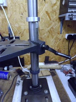
This photo shows the rack on the machine before modification. After modifying the pillar the rack is too low to be useful on most normal work.
Note that the end of the rack fits into grooves in the pillar flange and in the blue collar at the top of the rack.
Note that the end of the rack fits into grooves in the pillar flange and in the blue collar at the top of the rack.
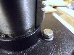
This is a close up showing how the rack fits into the pillar flange.
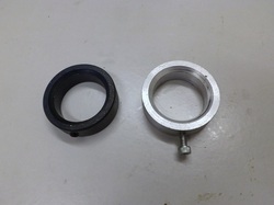
The blue upper collar also has a groove to guide the top end of the rack. Also shown in this photo is another collar machined to the same dimensions in aluminium.
Note that both collars clamp to the pillar using screws.
Note that both collars clamp to the pillar using screws.
The rack is now supported between two collars. Normally the collars are mounted as shown and this enable the table to be brought right up to the chuck. If extra room is needed it is a simple matter to loosen the screws in both collars and move them down.
