Improved chuck for taps.
When I made my pillar tool I fitted it with a conventional drill chuck. In practice this did not work very well with taps larger than M5 because the tap would slip in the chuck during tapping operations. I looked around for a simple four jaw chuck that would grip the tap by the square end in order to eliminate this problem but could not find anything. I remembered reading of a novel design of tap wrench published in Model Engineer in July 1964 by W.E. Briley. This was republished in Workshop Practice Series No 26. The tap wrench grips the tap on the square section at the end of the tap. I decided to try and convert this idea into a tap chuck that could be fitted to my pillar tool.
The principle of the device is illustrated in the diagram below:
The principle of the device is illustrated in the diagram below:
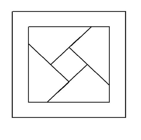
The diagram shows a square frame containing four truncated right triangles (hereinafter simply referred to as triangles). The triangles are not attached to the frame but are free to move around but constrained by the frame and the adjacent triangles. Note the square hole in the centre of the diagram. Imagine that the top left triangle is moved to the right then this pushes the top right triangle down, which pushes the bottom right triangle to the left and this in turn pushes the bottom left triangle up. The net result of moving the top triangle to the right then is to move all the triangles to the position shown in the next diagram.
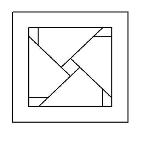
Note that all the triangles have moved and that the net result is that the square hole in the centre has decreased in size. Thus by moving any one of the triangles the size of the square hole in the middle can be varied. Note that the centre of the square hole does not move.
The base of the chuck is a flanged shaft with a socket to accept the drive shaft. The flange was made by silver soldering a 10 mm thick slice of 45 mm bar to a 19 mm steel shaft. After soldering the flange was faced and the shaft drilled and reamed 12 mm to accept the drive shaft.
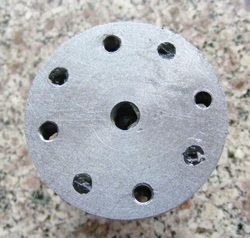
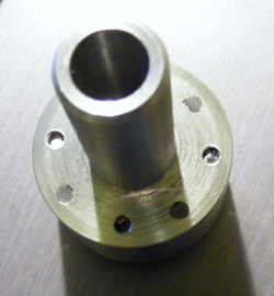
The flange viewed from the other side. Note the 6 mm hole in the centre of the flange. This is used later to centre the chuck jaws on the axis of rotation.
The outer ring of holes is for attachment of the aperture to the base of the chuck. These are not drilled until the chuck is finally assembled, see later.
The outer ring of holes is for attachment of the aperture to the base of the chuck. These are not drilled until the chuck is finally assembled, see later.
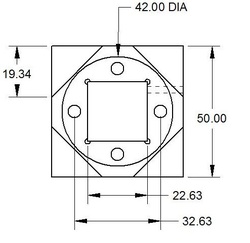
The next step was to mark out the components for the frame and the triangles, as shown, on a piece of 50 mm square x 10 mm thick steel plate. The edges of the plate were milled square prior to marking out.
Four 1.5 mm holes were drilled at the corners of the frame aperture and the four larger 3.3mm holes drilled.
The central frame aperture was then milled out using a 6 mm slot drill and then the corners filed out using a triangular file. A 2.5 mm hole (shown dashed) is drilled centred 3 mm from the aperture edge and at half the plate thickness. This hole is to allow access to the adjuster screw.
The four corners of the plate were then cut off. These were used to make the triangular chuck jaws. The triangles were set onto a 40 mm long vee block side by side with the 90 degree angle nestled into the vee. This was secured in the mill vice with two 3 mm packing pieces at either end so that the triangles were pressed firmly against each other. The triangles were tapped down into the vee as the vice was tightened. The top sawn surface was then milled until the long side of the triangles were 22.63 mm in length. The four triangles were then fitted into the aperture with the 90 degree angle pointing toward the middle. They should fit the aperture exactly. Using a 2.5mm drill through the 2.5 mm hole previously drilled though the aperture a hole was drilled into the triangular pieces ensuring that the drill penetrated the triangles but not the other side of the aperture. The triangle were then removed from the aperture. The hole in the triangle with the long hole was then opened out to 3.3 mm and tapped M4.
Each triangle was then mounted on parallels and one corner truncated so that the length of the long side was reduced to 17 mm.
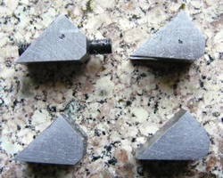
This shows the four truncated triangular pieces. The one that was tapped has been fitted with an M4 grubscrew that is slightly less than the frame aperture in width.
This is another view of the triangles showing how two of the triangles have been slotted to provide clearance for the screw. The slots are 5mm wide.
After making the triangular pieces they were case hardened by packing in a steel tube with case hardening compound and heating to bright red heat for 1 hour. After cooling each piece was then heated to bright red heat and quenched in water.
After making the triangular pieces they were case hardened by packing in a steel tube with case hardening compound and heating to bright red heat for 1 hour. After cooling each piece was then heated to bright red heat and quenched in water.
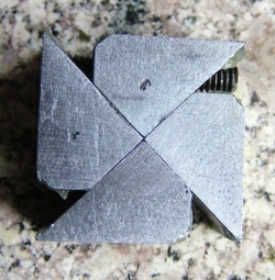
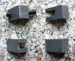
The four triangles fitted together with the adjuster screw.
The four triangles fitted into the frame.
When assembling the chuck a piece of 6 mm rod was inserted into the base flange. The aperture plate and triangles were then adjusted so that the centre hole was larger than 6 mm. This was then passed over the 6 mm rod and the chuck closed by turning the adjuster screw until it is firmly clamped onto the 6 mm rod. The 3.3 mm holes are then spotted through to the base flange. The base flange is then drilled through 3.3mm at the marked positions and the holes tapped M4. Using this procedure ensures that the chuck jaws are symmetric around the axis of rotation.
The base flange appears to have eight holes. This is because the tap broke off whilst tapping the last hole (it is always the last hole!!). The broken tap was broken off below the level of the flange and the four holes filled with epoxy putty. Four new holes were drilled and tapped after rotating the flange through 45 degrees.
The base flange appears to have eight holes. This is because the tap broke off whilst tapping the last hole (it is always the last hole!!). The broken tap was broken off below the level of the flange and the four holes filled with epoxy putty. Four new holes were drilled and tapped after rotating the flange through 45 degrees.
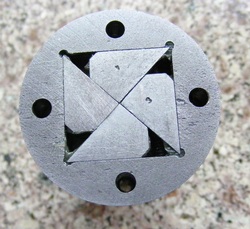
The final operation was to make a keep plate to retain the blocks. This was made from 3 mm steel plate with an 11mm centre hole and four 4mm countersunck holes for the retaining screws.
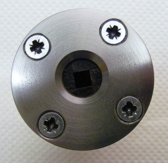
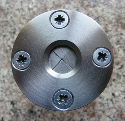
After final assembly the whole unit was chucked in the lathe and turned to a good finish on the outside.
After final assembly the whole unit was chucked in the lathe and turned to a good finish on the outside.
The main advantage of this chuck is that it grips the square end of a tap very firmly and slippage is virtually impossible. The one minor problem that has been found is that the square end of some taps are not quite square and this can allow them to rock slightly in one direction.
