Swing toolholder for internal threading.
Swing up tool holders for external threading greatly simplify the threading procedure if the lathe is equipped with facilities for forward and reverse rotation. A swing up tool for external threading is described here.
The design of a swing up toolholder for internal threading is much more difficult. Consider the following diagram:
The design of a swing up toolholder for internal threading is much more difficult. Consider the following diagram:
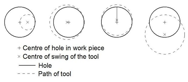
On the left is shown the situation when the swing radius of the tool is much less than the diameter of the hole being threaded. Here the situation is very similar to external threading since the tool can swing up and away from the hole. However as the hole becomes smaller problems arise. If the centre of rotation of the toolholder is to the left of the hole centre, as shown in the second drawing, then if it swings up it will in fact dig deeper into the hole and a jam up is inevitable. The same situation applies if the centre of rotation of the tool is even slightly higher than the centre of the hole, as shown in the third drawing. The fourth drawing shows the situation if the centre of swing of the tool is below the centre of the hole. Here the tool moves up and out from the internal surface of the hole and the danger of digging in is removed. The design of the toolholder described here is based on the keeping the centre of swing of the tool below the centre of the hole.
Prototype development.
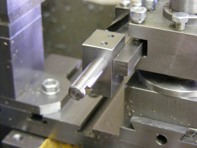
In order to test the concept of a new toolholder a prototype was constructed as shown in the photo above. It consists of a large block mounted on the tool post. There is a smaller block, the swing block, at the front that is pivoted on a 6 mm rod passing through the large block. The swing block is also bored for the cutter (for brevity, I am using "the cutter" to describe the cutting tool proper and the bar in which it is held). On the back of the large block and attached to the other end of the pivot rod is a chunk of metal that acts as a weight to keep the small block vertical. The travel of the weight is limited by the stop screw visible resting on the top of the block. Thus the swing block can tilt backwards on the pivot rod but in the forward direction its travel is limited by the stop screw.
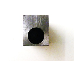
The block that mounts on the toolpost is drilled out with a 6 mm hole close to the base of the block
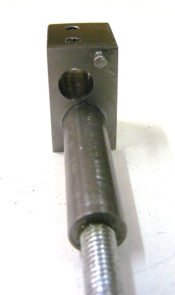
This shows the block, the spindle attached to the weight and the swing block holding the tool. The block, weight and tool are all held to the spindle by M4 socket head screws.
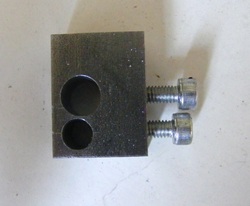
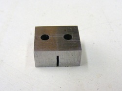
This shows the swing block. The bottom hole is 6 mm diameter for the spindle and the larger one is 8 mm to hold the cutter. Note that the centre of the 8 mm hole is to the right of the centre of the 6 mm hole. This ensures that the cutting forces on the tool force the spindle to try to rotate against the stop on the weight.
This shows a piece of aluminium tube threaded with a 1 mm pitch metric thread using the toolholder.
The toolholder shown above was a development project to test out the concept of an internal swing toolholder. It worked very well on aluminium. When used for threading the swing block maintains its vertical position as the cutter cuts the thread. On the return pass the swing block tilts back allowing the cutter to ride on the flanks of the previously cut thread, just the same as with an external swing up toolholder.
However, when using the tool to cut a thread in harder materials, such as steel, the result was less than satisfactory due to lack of rigidity. This lack of rigidy was traced to three main causes: the use of grub screws to secure the small block to the pivot rod, the use of only one screw to clamp the cutter into the swing block and the torsional flexibility of the pivot rod itself. The net result of these problems was movement of the cutter and chatter leading to poorly formed threads, particularly where the cutter first enters the workpiece
The concept of the toolholder obviously worked so the tool holder was redesigned to eliminate the sources of lack of rigidity. At the same time the toolholder was redesigned to allow it to be clamped in a conventional toolpost toolholder and to use a spring rather than a weight to maintain the swing block upright.
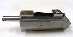
The improved version.
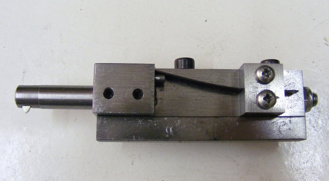
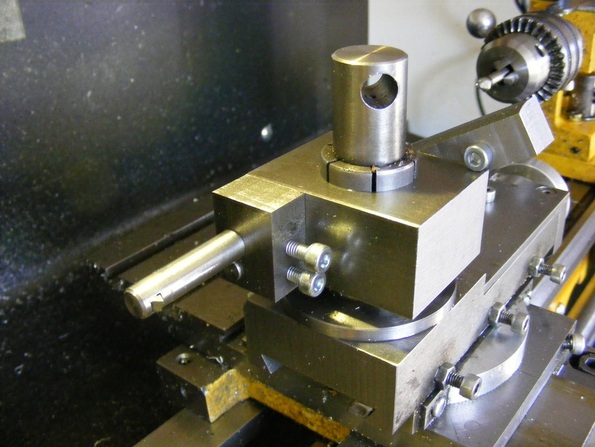
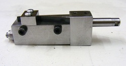
The improved version is shown above. The pivot bar has been increased in size to 10mm and the swing block secured to it with epoxy resin. This eliminates any movement. At the bottom of the photo is an 8 mm square bar that can be clamped in a conventional toolpost toolholder. To the left is the small swing block. Note that the clamp bar now functions also as a stop as can be seen in the page header photo. The cutter is secured in the swing block using two screws to eliminate the possibility of any movement. On top of the tool holder is a leaf sping that ensures that the swing block is held firmly against the square bar. The spring is not attached to the block but merely presses against a small pin attached to the swing block.
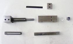
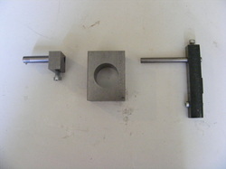
This shows all the parts of the toolholder. In the centre row, on the left is the swing block and pivot rod, next right is the main block and to right are the washer and locknut that secure the pivot rod in the main block. At the top are shown the leaf spring and the spring retainer block. Below are the cutter and the clamp bar.
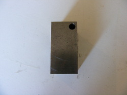
The swing block is made from a 25 mm length of 16 x 19 mm bar. The holes for the pivot rod and cutter were drilled and the 10 mm pivot rod attached using epoxy resin. This eliminates any possibility of slackness at the joint. The pivot rod was drilled and tapped to accept a length of M6 studding that was fixed in place using Loctite. The swing block was faced both side once the epoxy had set to ensure that they were accurately perpendicular to the pivot rod.
The two holes in the top of the swing block are for the M4 grub screws that secure the cutter in the swing block.
The centre of the cutter hole is 2 mm offset from the axis of the pivot rod.
Also note the 2.5 mm pin protruding from the swing block. The spring rests against this.
The two holes in the top of the swing block are for the M4 grub screws that secure the cutter in the swing block.
The centre of the cutter hole is 2 mm offset from the axis of the pivot rod.
Also note the 2.5 mm pin protruding from the swing block. The spring rests against this.
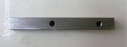
The main block is a 50 mm length of 16 x 19 mm steel bar. A 10 mm hole was drilled and bored the entire length of the bar to give a sliding fit on the pivot rod. Both ends of the bar were faced.
The spring retaining block was made from a piece of 8 mm plate from the scrap box. This was slit with a junior hacksaw to a depth of 5 mm. The two 3 mm holes are for the screws that bolt the retainer to the main block.
The sping is just a length of Junior hacksaw blade (Eclipse)with the teeth ground off. It is 4.5 mm wide.
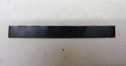
The clamp bar is a length of 8 mm square bar. It runs the whole length of the toolholder and also acts as a stop for the swing block.
This shows the clamp bar side of the toolholder. The spring just passes through the spring retaining block and is not held in any way. The spring pressure holds it in place.
Note the ends of the two screws securing the clamp bar in place.
Note the ends of the two screws securing the clamp bar in place.
The M4 screws securing the clamp bar pass right through the main block.
The pivot rod passes through the main block and is secured by a thick washer and a lock nut. This can be seen on the left hand side of the photo. The nut is tightened up hard and then slackened off a little to allow the swing block to swing easily.
The pivot rod passes through the main block and is secured by a thick washer and a lock nut. This can be seen on the left hand side of the photo. The nut is tightened up hard and then slackened off a little to allow the swing block to swing easily.
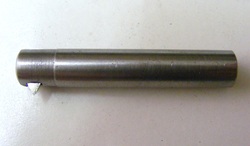
The tool is made from a 48 mm length of 8 mm diameter steel. A 3.2 mm hole was cross drilled at one end and then broached out to 1/8" square for the cutter. In the lathe the rod was drilled out from the other end to 3.3 mm until it broke into the broached hole. The end was tapped M4 for a length of 10 mm. The cutter is a short length of 1/8" square HSS that is ground to a 60 degree point, and secured by an M4 grubscrew bearing on a 3 mm diameter push rod which in turn bears on the cutter.
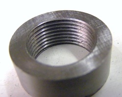
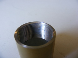
This shows a steel ring that has been threaded 1 mm pitch using the tool. The threads are clean even at the point where the tool enter the workpiece. There was no sign of chatter when machining the thread.
This improved version of the tool works very well in all common materials including steel. It is compact and very convenient to use.
