Laser centreing device Mk 2
This device was constructed to replace a similar device that was built around laser pointer, see here. The previous device worked well but the laser pointer eventually failed and a suitable replacement could not be found.
This new device is built around a cheap and readily available laser diode. The laser diode is 6 mm diameter and can be powered directly from a 3 V supply. There are many different suppliers of these diodes on ebay and they cost typically around £1 each.
This new device is built around a cheap and readily available laser diode. The laser diode is 6 mm diameter and can be powered directly from a 3 V supply. There are many different suppliers of these diodes on ebay and they cost typically around £1 each.
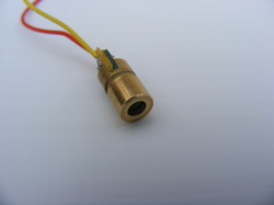
The laser diode is 6 mm diameter and the front nose piece rotates on the back piece to focus the beam. The front piece house a small lens and a spring whilst the back piece contains the laser diode.
The connections are by flying leads at the back of the diode. The flying leads are connected to copper clad boards at the back of the diode. These boards are slightly wider than 6 mm.
On receipt the diode was energised with a three volt battery and the front rotated to give a small parallel beam.
The connections are by flying leads at the back of the diode. The flying leads are connected to copper clad boards at the back of the diode. These boards are slightly wider than 6 mm.
On receipt the diode was energised with a three volt battery and the front rotated to give a small parallel beam.
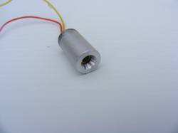
The laser diode was fitted into a small piece of 10 mm diameter aluminium. This was 19 mm long and drilled out all the way through with a 4 mm drill. It was then drilled out to a depth of 16 mm with a 6 mm drill and then to a depth of 10 mm with a 7 mm drill.
The front face was chamfered with a 60 degree centre bit.
The laser diode was secured in the tube using a smear of epoxy resin.
The front face was chamfered with a 60 degree centre bit.
The laser diode was secured in the tube using a smear of epoxy resin.
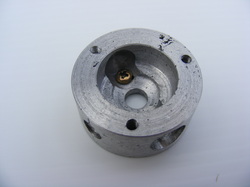
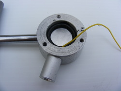
The housing was machined out of a piece of scrap aluminium. It was actually a cut out from a casting made with a hole saw. After machining it was 33 mm diameter and 15 mm thick.
It was cross drilled with a 10 mm drill to take the laser diode housing. This should be tight fit. It was also cross drilled at 75 degrees to the laser axis with 2.5 mm drill which was then tapped M3.
It was bored out to 20 mm for just over half the depth to accommodate the battery.
A small M2.5 hole was drilled in the bottom of the housing. This is for one of the laser diode connections.
The three M3 tapped holes on the top surface a for securing the cover.
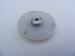
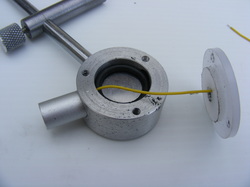
The cover is 33 mm diameter and 6 mm thick. It is made of polyethylene.
The centre is drilled and tapped M6 for the aluminium plug.
The plug is machined from 10 mm aluminium rod. This is turned down to 6 mm for a length of 5 mm and threaded M6. It is drilled out 2.5 mm and tapped M3.
The three 3.5 mm holes around the perifery are for the screws that secure the cover to the housing.
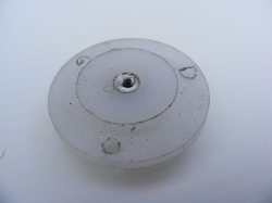
The underside of the cover is turned down to 20 mm diameter for a distance of 3 mm to fit into the housing recess.
Note the small 1.5 mm hole just to the left of the aluminium plug. This is for the other laser diode lead to pass through and connect to the plug.
Note the small 1.5 mm hole just to the left of the aluminium plug. This is for the other laser diode lead to pass through and connect to the plug.
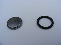
The battery, left, is a type CR2032. This is a high capacity 3 volt lithium cell.
On the right is a two mm O-ring that is used as a spacer.
On the right is a two mm O-ring that is used as a spacer.
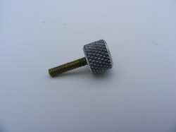
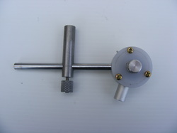
This is the screw that is used to turn on the laser diode. It is an M3 brass screw with a knurled aluminium knob.
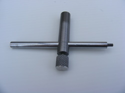
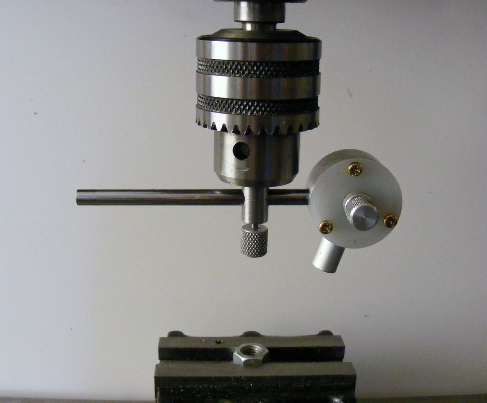
The housing mounts on the end of the cross bar. This is threaded M3 for a length of 6 mm.
The cross bar slides in a length of 10 mm steel bar that is chucked in the mill. The knurled knob is used to lock the cross bar in a fixed position.
The cross bar slides in a length of 10 mm steel bar that is chucked in the mill. The knurled knob is used to lock the cross bar in a fixed position.
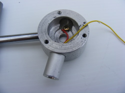
Here the housing has been screwed onto the cross bar and the red lead from the laser diode has been connected to the M2.5 screw in the bottom of the recess.
The battery and O-ring have been inserted in the housing.
The other lead from the diode passes through the 1.5 mm hole at the side of the aluminium plug in the cover and the bare conductors trapped under the plug flange.
Here the cover has been put on the housing and screwed down.
The brass screw screws into the aluminium plug and makes contact with the battery and turns the laser diode on.
Undoing the brass screw one turn turns the laser off
The brass screw screws into the aluminium plug and makes contact with the battery and turns the laser diode on.
Undoing the brass screw one turn turns the laser off
The new unit works in a similar fashion to the original.
