Lathe motor control
When single point threading I rarely use the threading dial. I leave the half nuts engaged throughout, and stop the spindle at the end of each cut, then reverse the motor to take the carriage back for the next cut. The motor must be stopped at the same place at the end of each cut, and this section deals with an autostop device I made to accomplish this. The device is complemented by the swing up threading toolholder, which avoids the need to retract the tool during the carriage reverse. This combination of autostop and swing up toolholder leads to a very efficient system for thread cutting. The only manual operations needed are to start the carriage moving to take a cut, and when it has stopped, reverse the motor to take it back, stop again, advance the tool, set the motor to forward and restart it for the next cut.
Unlike the 12 V motorised leadscrew, cross slide motor, autostop and their controller described in earlier sections, this modification involved working on both the lathe's AC mains supply and on the DC feed from the control board to the motor. The voltages involved can be lethal, so special care must be taken over wiring up and earthing (grounding) of things like metal enclosures. If you are not experienced and competent in such matters, do not attempt this modification.
The features I wanted to incorporate in the design were:
1. Consistency of the stopping point. I find the device accomplishes this. For example cutting an M6 thread (1 mm pitch on 6 mm stock) at 200 rpm repeatability is within about 0.1 mm (0.004").
2. Obviate the possibility that, once the carriage has stopped after making a cut , it might accidentally be restarted towards the chuck, instead of being reversed. A relay and substantial power diode have been placed in the DC supply to the motor to deal with this.
3. Utilise the same limit switch as I fitted to stop the 12 V leadscrew motor, to avoid cluttering up the lathe with a second switch with a similar function. That switch will only carry low voltages and currents so would need to control the relay mentioned above, and another in the AC supply to the main control board. This means that the same 12 volt plug in wall transformer can be used to power whichever is in use of the leadscrew motor, the cross slide motor or the low voltage side of the carriage autostop now being described. It would of course be unwise to bring mains voltage out to a switch mounted where it might be showered by chips and coolant.
4. The modifications should allow use of the lathe for normal manually controlled operations (including the use of the half nuts for threading) without anything needing to be detached or altered for the transition.
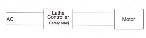
Here is a block diagram of the normal "ex factory" set up. The "safety relay" is the one incorporated by the manufacturer which cuts of the power when the forward/reverse switch is operated or whenever the AC power is interrupted.
The modifications:
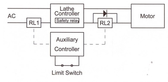
RL2 and its bypass diode ensure that the motor can only be restarted in reverse, after the limit switch has brought the carriage to a halt. But RL2 is switching the DC line. Though small relays are happy switching AC mains and low DC voltages, they are prone to arcing and rapid failure if used to switch DC voltages of the order used to power the lathe motor - 180V or 90V, depending on your country. One of the functions of the Auxiliary Controller is to make sure that RL2 only operates when the DC line is dead.
The full sequence of events is as follows:
1. When a cut is being taken, the carriage moves towards the headstock, eventually opening the limit switch. This triggers timing circuits in the auxiliary controller. One timer immediately sends a 12V pulse lasting about a second to the coil of the normally closed relay RL1 in the AC line.
2. The pulse opens RL1, switching off the AC mains supply to the Lathe Controller. This causes:
(a) the motor, spindle, leadscrew and carriage to stop, and
(b) the safety relay built into the Lathe Controller to open. This leaves the Lathe Controller and the DC feed to the motor electrically dead, so that the motor cannot restart when RL1 closes again at the end of the one second pulse.
3. After another 2 or 3 seconds a second timing circuit sends a continuous 12 V signal to RL2 in the DC motor feed. RL2 opens. As just stated, the DC motor feed is now dead, so no arcing can occur.
4. The operator sees that the spindle and carriage have stopped at the end of the cut, so the next thing is to back the carriage away in readiness for the next cut. The speed control is returned to zero and the forward/ reverse switch is flipped to reverse. These actions cause the safety relay to close.
5. Though the safety relay has now closed, RL2 in the DC feed remains open, because the carriage is still holding the limits switch open. However, the power diode allows current to bypass RL2 in one direction only - the one that will turn the main motor in reverse - when the speed control is advanced. If the operator has inadvertently left the motor switched to Forward, the diode and the open relay contacts of RL2 block DC current to the motor.
6. If, and only if, the operator has selected Reverse, the motor then starts and the carriage backs away from the limit switch, which reopens and terminates the second timer in the Auxiliary Controller. The coil of RL2 de-energises and its contacts close. The forward voltage drop across the diode is only about 1 volt and the relay will handle this easily.
7. The carriage continues to move back until the tool is clear of the end of the work, whereupon the operator stops the motor, increases the depth of cut, switches to Forward and restarts the motor for the next pass.
The diode across DC relay RL2 needs to carry the full motor current. I used a 600PIV 6A power diode. This has proven satisfactory in service.
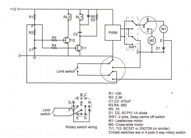
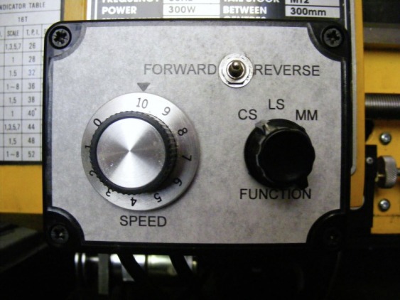
The circuit diagram shows the Auxiliary Controller, which comprises Tr1 and Tr2 and their associated components including RL1 and RL2. Only the coils of the relays are shown and these activate the relay contacts in the high voltage AC and DC lines shown in the previous diagram. Also shown is the low voltage PWM speed control and reversing switch SW1 for the leadscrew and cross slide motors M1 and M2. The rotary switch (4 pole 3 way) selects the function required - Auxiliary controller for thread cutting, leadscrew motor or cross slide motor, and also brings the limit switch into play for the first two of those functions. Wiring of the rotary switch is shown. As seen in the header photo, it is labelled MM (main motor), LS (leadscrew motor) and CS (cross slide motor).
The Auxiliary Controller works as follows: when the limit switch opens the voltage at point F rises instantly turning on transistor Tr1, which sends a pulse through C2 into relay RL1 causing the contacts to open. The pulse lasts about 1 second (during which lime the safety relay opens) and RL1 then closes. In the meantime C1 has been charging and the voltage on C1 is eventually sufficient to turn on transistor Tr2. RL2 then opens and remains open until the limit switch is closed. The time delay before RL2 actuates is 2-3 seconds.
The circuitry is constructed in two parts. The rotary function switch (MM,LS, or CS), together with the Forward/Reverse switch and speed control for the cross slide and leadscrew motors are mounted in a small ABS box. This box, shown in the header photo, is mounted on the front of the lathe electronic cover. The function switch selects between controlling the cross slide motor (CS), the leadscrew motor (LS) or the main lathe motor. The relay control circuitry and the relays are mounted in a second box at the back of the lathe behind the change gear cover. All the high voltage lines enter this box at the bottom through cable glands and the low voltage lines via grommeted holes. I used an ABS box so there was no earthing requirement other than the mounting screws but if a metal box were used then it would need to be earthed.
As stated earlier, the autostop works well and I have cut threads at quite high speeds (200 rpm). The autostop point is repeatable at this speed to 0.1 mm. At higher speeds I think that chuck inertia would become the limiting factor on repeatability.
Thanks are due to Ian Foster for helpful discussions during development of the controller circuit.
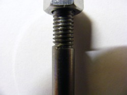
This photo is an example of what is possible using the autostop for screw cutting. The M6 thread was cut without a run out groove, the end point being only controlled by the autostop.
