Lathe motor cooling
The lathe motor has a fan attached to the armature shaft that blows air through the motor to remove heat. This system works well with the motor running at high speed. However, when turning large diameter stock then it is necessary to slow the motor right down and in these circumstances the air flow through the motor is low and, on a long job, the motor can get very hot.
A number of users have fitted an external fan, usually a small computer fan, to pass air through the motor continuously to avoid this overheating at low speed. These modifications usually involve fitting some sort of sleeve over the motor casing with the fan mounted at one end, see for example http://andysmachines.weebly.com/motor-cooling-fan.html
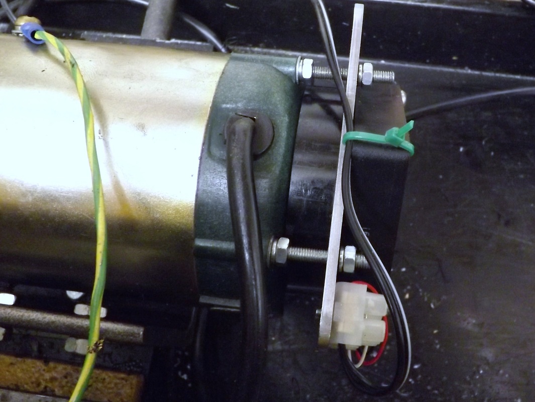
I was keen to make a similar modification to my lathe but when I started looking at how to make the mod I found that the motor had not only the cable lead in but also the two brush mounting sticking out from the casing and this makes fitting a sleeve over it tricky. I have therefore adopted a different approach whereby the fan is mounted on a plate and the plate is used to clamp a short length of ducting ( the black spacer between the motor and the plate) to the motor casing using extended studs replacing the original motor screws, as shown above.
A number of users have fitted an external fan, usually a small computer fan, to pass air through the motor continuously to avoid this overheating at low speed. These modifications usually involve fitting some sort of sleeve over the motor casing with the fan mounted at one end, see for example http://andysmachines.weebly.com/motor-cooling-fan.html
I was keen to make a similar modification to my lathe but when I started looking at how to make the mod I found that the motor had not only the cable lead in but also the two brush mounting sticking out from the casing and this makes fitting a sleeve over it tricky. I have therefore adopted a different approach whereby the fan is mounted on a plate and the plate is used to clamp a short length of ducting ( the black spacer between the motor and the plate) to the motor casing using extended studs replacing the original motor screws, as shown above.
The first task was to remove the screws holding the bell end of the motor to the casing. These were removed one at a time and replaced with a 55mm long M4 studs. The bell end was then held using a washer, spring washer and nut to the motor casing. The studs protrude 25 mm from the motor.
Doing each stud individually avoids the problem of the bell end coming off and the necessity to reassemble the motor and the brushes
Doing each stud individually avoids the problem of the bell end coming off and the necessity to reassemble the motor and the brushes
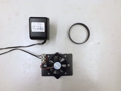
This shows the other parts of the conversion. This consist of the motor plate, a 24V fan, 24V power supply, and a short length of ducting.
The ducting was a short piece of rainwater downpipe with an OD of 68 mm (nominal bore 2.5 inches). This was cut off roughly square using a hacksaw and the end machined in the lathe so that the finished length was 12 mm.
The ducting was a short piece of rainwater downpipe with an OD of 68 mm (nominal bore 2.5 inches). This was cut off roughly square using a hacksaw and the end machined in the lathe so that the finished length was 12 mm.
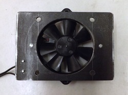
The fan is mounted on a piece of 3 mm steel plate 100mm x 70mm. This was drilled out centrally to 60 mm with a holesaw in the pillar drill, using a slow speed and much lubricant.
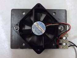
This shows the other side of the plate. The fan is a 60 mm fan salvaged from some old electonics.
The plate was drilled 3.3 mm and tapped M4 for the fan mounting holes 72 mm apart.
The four 5 mm holes around the fan are for mounting the plate to the lathe motor studs.
The small piece of "choccy block" serves for the connections of the power supply to the motor. This is attached to the plate with two M2.5 screws. The motor had three leads only the red and black were connected.
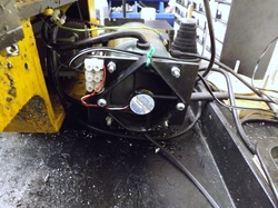
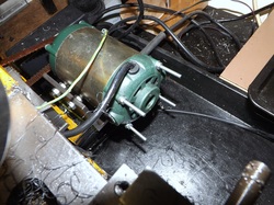
The plate was then fitted on the motor studs, with the short duct piece in between, and secured in place with M4 nuts. These nuts were tightened evenly to clamp the duct in place.
The fan in the motor is arranged so that with the lathe turning in the normal forward direction the air flows through the motor from the shaft end to the brush end. This means that the external fan must suck air through the motor. It is important to check that the flow through the motor is correct or the motor fan may be working in opposition to the external fan. If necessary, then the external fan can be turned over so that both tans are pushing air in the same direction.
When the lathe is used in reverse then the two fans will oppose each other but normally use of the lathe in reverse is for very short periods (e.g. reversing out when screw cutting) so I do not anticipate this being a problem.
When the lathe is used in reverse then the two fans will oppose each other but normally use of the lathe in reverse is for very short periods (e.g. reversing out when screw cutting) so I do not anticipate this being a problem.
