Lathe spindle handle
Being able to turn the lathe spindle by hand is very useful for some operations. For example,when threading to a shoulder, a slow speed and the ability to stop at exactly the right point is very important. If done under power there is the potential to crash the tool into the shoulder which could cause damage to the gears, the belts, the tool and the work. The human hand can turn the spindle very slowly and it can also feel when there is an abnormal resistance which gives much more control.
Another instance when a spindle handle is useful is when turning large diameter work. Here the minilathe can be short on available torque from the motor. Turning by hand can provide much more torque than the motor.
When turning coarse pitch threads or using form tools the motor torque may be insufficient but hand turning can be used to good effect.
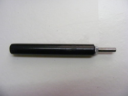
First spindle handle.
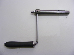
The first spindle handle I made is shown. It consists of a piece of 20 x 1.5 mm steel tube that inserts into the spindle bore. There are four longitudinal slits in the right hand end end of the tube. Also at the right hand end is a cone that can be drawn into the split end of the tube to expand it so that it grips the bore of the spindle. The cone is drawn into the handle by a threaded rod that emerges from left hand end of the tube where a nut can be tightened against the boss on the left hand end. A handle is attached to this boss as shown.
I originally envisage four 50 mm tommy bars that would screw into the boss to turn the spindle and the holes for these can be seen in the photo. It was however hard work turning the spindle with such short handles that I eventually removed them and replaced then with the 200 mm handle shown. This was much easier to use.
There was however a down side to changing the original design. Firstly the handle sweeps out a considerable arc and secondly the handle is not balanced. One day I turned the lathe on whilst the handle was in the spindle. The whole lathe vibrated violently because of the imbalance and several items were knocked by the handle. Fortunately no real damage was done but the potential for serious damage to the machine and to the operator was clearly demonstrated. I have been extremely careful ever since.
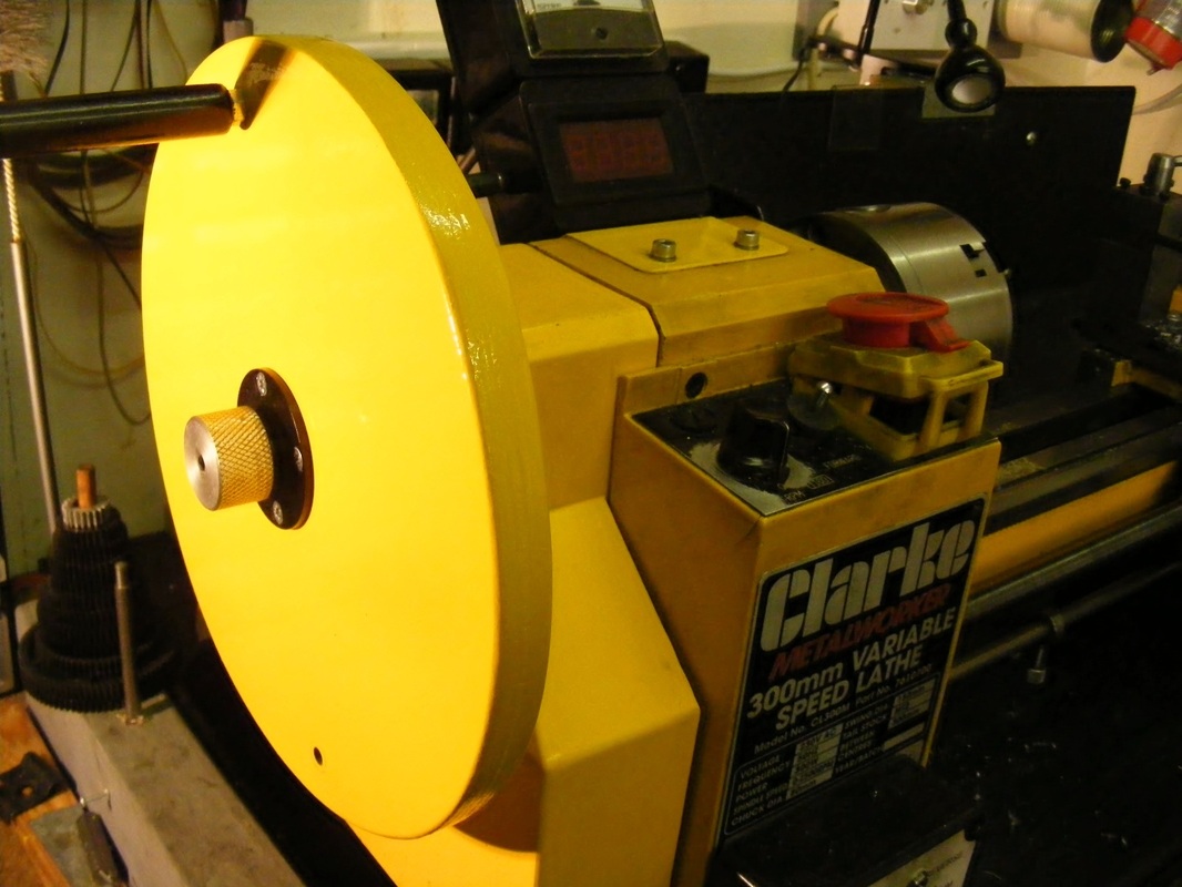
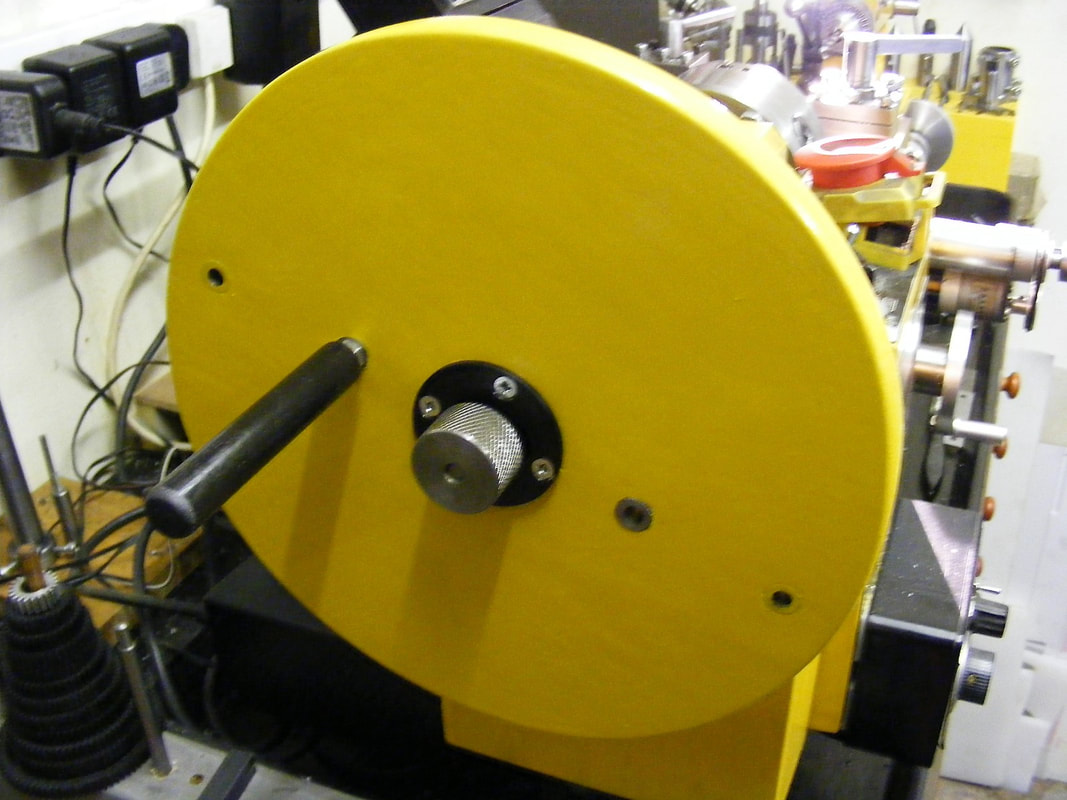
New spindle handle.
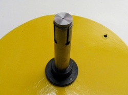
The new spindle is shown in the page header. It is based on the a design by Ted Hanson published in Home Shop Machinist.
It consist of a large wheel, 250 mm diameter and 19 mm thick. This was cut from a sheet of 19 mm birch ply using a small woodworking bandsaw. A 6.5 mm hole was drilled in the centre. Two 12 mm holes were also drilled on a diagonal at a radius of 105 mm from the centre.
Two steel inserts were made from 12 mm steel round. The inserts were 19 mm long and there were drilled out 6 mm. The outer surface was lightly knurled. The inserts were then pressed into 12 mm holes in the wheel. These inserts provide a hole for inserting a handle.
The edges were smoothed and rounded and the wheel was painted to match the lathe.
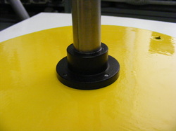
The flanged boss was turned from a piece of 50 mm steel round. This was chucked, faced and turned down to 30 mm diameter fro a length of 14 mm. It was then cut off 20 mm from the end, using the bandsaw, to leave a 6 mm flange. This was rechucked in the lathe and the sawn surface was then faced. A 20 mm diameter hole was drilled and bored through the boss for the 20 mm tube.
Whilst the boss was in the lathe it was marked out for for four holes equally spaced on a 20 mm radius from the centre of the boss. These holes were drilled and tapped M4.
Whilst the boss was in the lathe it was marked out for for four holes equally spaced on a 20 mm radius from the centre of the boss. These holes were drilled and tapped M4.
A 105 mm length of 20 x 1.5 mm steel tube was cut. Four equally spaced 6 mm holes were drilled 25 mm from the end of the tube. Four slits were then sawn from the end of the tube to meet the holes as shown.
The other end of the tube was thoroughly degreased. The flanged boss was also degreased. The two components were then joined using high strength epoxy resin.
The other end of the tube was thoroughly degreased. The flanged boss was also degreased. The two components were then joined using high strength epoxy resin.
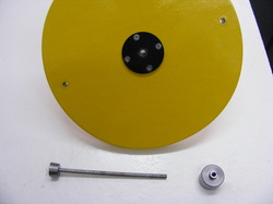
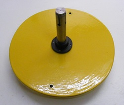
A steel disc 50 mm x 3 mm thick was machined from steel plate. This was centre drilled 6.5 mm and four 4.5 mm holes were drilled at 20 mm radius to match the holes in the boss. These holes were countersunk for M4 screws.
This plate was used to mark out the holes in the wooden wheel. A 6.5 mm drilll was used to line up the plate with the wheel and then the 4 x 4.5 mm holes were drilled through.
The boss, wheel and plate were assembled together using four 4 mm countersunk screws
Also shown in the photo are the cone to expand the tube and the knurled nut.
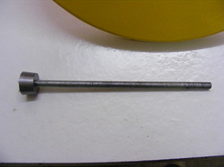
The expander cone was turned on the end of some 19 mm steel round. The topslide was set to form a 6 degree taper. It was centre drilled 5 mm and then tapped M6. The cone was then parted off 11 mm from the end.
The threaded part was just a piece of 6 mm threaded rod 150 mm long.
The cone and threaded rod were degreased and screwed together with a drop of Loctite on the threads.
The threaded part was just a piece of 6 mm threaded rod 150 mm long.
The cone and threaded rod were degreased and screwed together with a drop of Loctite on the threads.
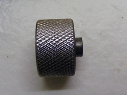
The knurled nut was made from 30 mm round steel bar. This was faced and then knurled for a distance of 24 mm. It was bored out 5 mm to the same depth. The end was then turned down to a diameter of 10 mm for a length of 4 mm. A 6 mm tap was chucked in the tailstock and this was used to start a thread in the nut. The nut was then parted of 22mm from the end.
The nut was gripped in the bench vise and the thread extended all the way through.
The nut was gripped in the bench vise and the thread extended all the way through.
The handle is made from a piece of 15 mm wooden dowel. This was drilled through with a 5.5 mm drill to a depth of 50 mm. A 70 mm length of 6 mm round steel was threaded M6 for about 50 mm and a nut was screwed on. A little PVA adhesive was spread on the thread and in the dowel hole and the steel piece screwed into the wood.
The wood was primed and then painted black.
The handle is not designed to be permanently in place. It is simply pushed into one of the insert holes when needed
The wood was primed and then painted black.
The handle is not designed to be permanently in place. It is simply pushed into one of the insert holes when needed
Update.
The handle shown above works very well but because of the large swing it becomes quite tiring especially for rapid return of the carriage after a threading cut. To lessen this problem a small modification was made.
|
Two additional inserts were pressed into the wooden wheel at about half the distance to the outside edge. This gives a much smaller swing and enables a more rapid rotation. All other parts of the handle remain the same.
|
