Mill Z axis DRO
The Z axis adjustment on my X1 mill is not very accurate. In fact the scale divisions on the quill adjuster knob are stated to be 0.05 mm but in fact they are 0.06 mm. I came across a digital tyre depth guage on eBay that I thought could perhaps be modified to provide a direct readout. These units have a nominal range of 0-25 mm, a resolution of 0.01mm and they are very cheap at anything from £3 upwards. The X1 has a quill travel of 28 mm so the range was about correct.
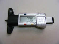
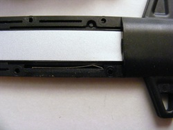
This shows the unit as received. My first impressions were that it was a bit cheap and nasty because the case and probe were all made from plastic. However after a lot of testing the unit appeared to give accurate and reproducible measurements
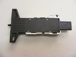
This shows the back of the unit. This is normally covered by a metallic sticky label that covers all the screws. This was peeled off and the back cleaned up with white spirit to remove the adhesive. There are four screws securing the back on. These were removed and the case opened.
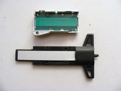
The electronics are all housed on the front part of the case (at the top in the photo).
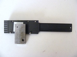
The mechanical parts are shown below and they consist of the black plastic track, the grey slider and a small leaf spring to provide a friction fit of the slider in the track.
The mechanical parts are shown below and they consist of the black plastic track, the grey slider and a small leaf spring to provide a friction fit of the slider in the track.
This shows the small leaf spring at the bottom of the track.
The winged part of the track (on the right of the picture above) was cut off and the end cleaned up with a file. The spring was discarded and the probe on the sliding part was cut off. A 3 mm hole was drilled at one end of the slider.
A metal plate and spacer were attached to the underside of the track using an M2 countersuck screw. Note the 3 mm hole at the end of the slider.
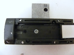
This shows the other side of the track and the M2 screw securing the plate and spacer. The whole unit was reassembled.
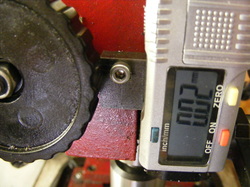
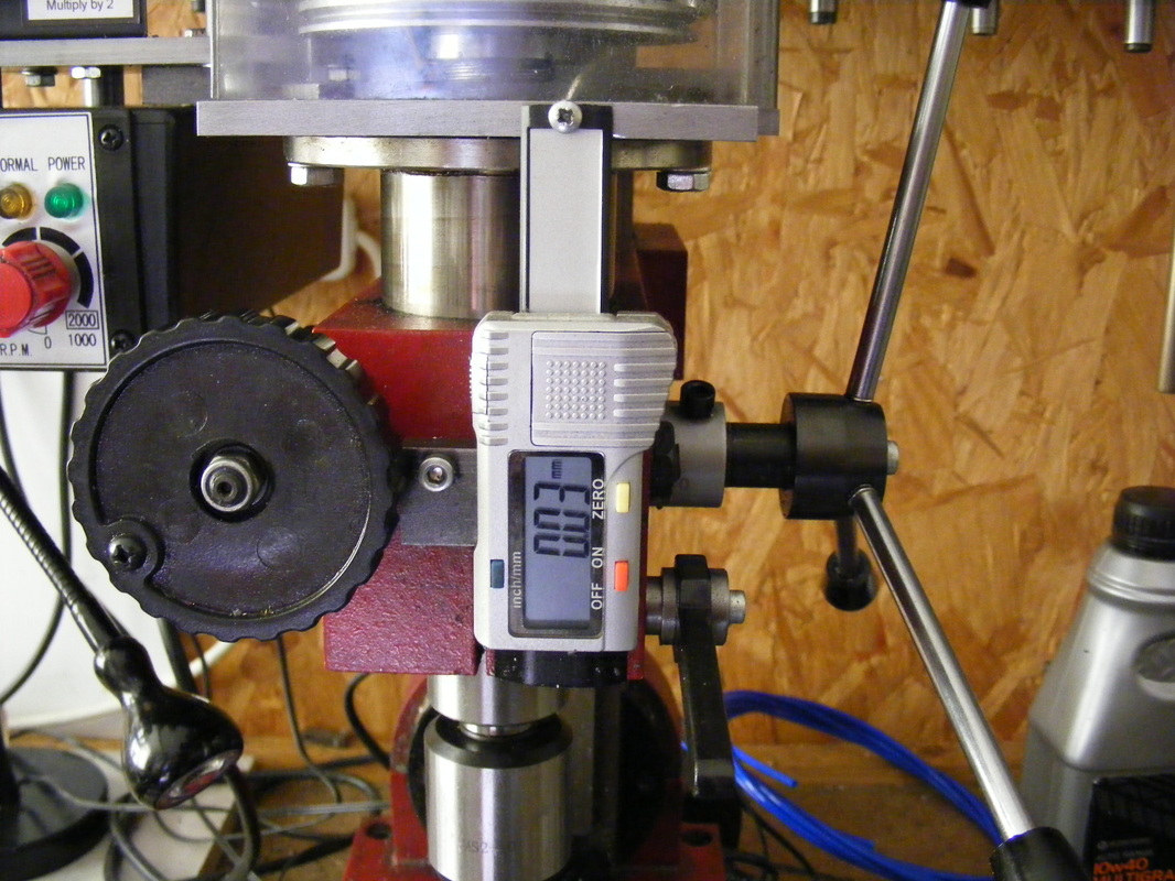
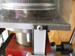
The metal plate is attached to the headstock casting using an M4 screw. The screws into one of the holes that was used to hold the transparent safety guard to the front of the machine. (An alternative safety guard has been in use for a long time prior to installation of the DRO)
The upper end of the slider is attached to the upper deck of the mill that supports the motor.
My mill has been modified to have a belt drive from the motor to the spindle. However, alternative fixing of the top end of the slider to the upper deck on a conventional gear driven mill should also be possible.
My mill has been modified to have a belt drive from the motor to the spindle. However, alternative fixing of the top end of the slider to the upper deck on a conventional gear driven mill should also be possible.
One word of warning regarding the tyre depth guages is that the readings become erratic when the battery becomes exhausted.
