Pillar tool
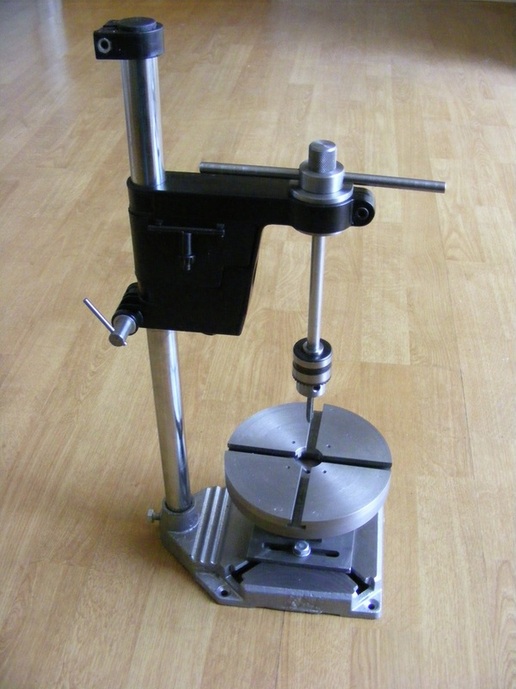
A pillar tool is a useful piece of equipment. It can be used for tapping. It can also be used for stamping number or letters onto dials. The basic geometry ensures that the tap or stamp is presented at right angle to any horizontal surface mounted on the base or on the table.
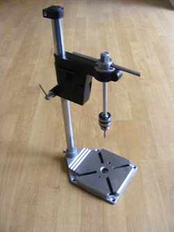
This pillar tool started life as a drill stand that was purchased in Lidl for £9.99.
This pillar tool started life as a drill stand that was purchased in Lidl for £9.99.
The Lidl "Powerfix" drill stand
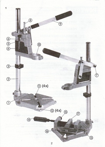
The drill stand is intended to hold a portable electric drill vertically so that it can be used as a pillar drill. It consists of a cast iron base (1) and a pillar (2). The electric drill is held in the clamp (10). This is designed to accept any drill with a 42 mm collar. The part labelled 10 slides on the pillar and can be locked in place with a clamp screw. Part 10 consists of two castings that are spring loaded together. When the lever (7) is operated then the lower of the two castings separates smoothly from the top fixed casting thereby moving the drill downwards into the workpiece which is held securely in the vice (16). The vice is a lightweight alloy casting witha quick release and adjust button(15).
To convert the drill stand to a pillar tool the base and pillar are utilised together with the sliding clamp.
The sliding clamp was modified as follows:
1. The clamp was removed from the pillar and stripped down to the two castings.
2. The depth stop(8) was removed together with the internal spring. The depth stop was replaced with an M10 steel bolt and nut, locking the two castings permanently together. The nut was tightened with the clamp assembled on the pillar to ensure alignment of the two castings.
3. All extraneous appendages, such as the mountings for the handle components and the depth guage scale, were sawn from the clamp and filled flush with the body.
4. The underside of the clamp is a hollow section and this was partially filled with wood.
5. All unwanted holes and the hollow underside where then filled with "Plastic Padding". Once this was set then the whole unit was sanded to smooth finish and then sprayed with black paint.
A cylinder of metal was machined to fit snugly into the base of the pillar tube so that the the securing bolt on the base did not crush the tube.
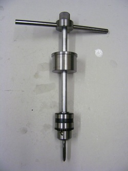
The tapping head consist of four parts: the chuck, the shaft, the collar and the handle.
The chuck is a 10 mm chuck with a 3/8" 24tpi thread that was salvaged from the scrap box.
The shaft is a length of 10 mm rod. One end was turned down to 3/8" and then screw cut to accept the chuck. The other end was threaded with a die to M10.
The collar is a 38mm length of 45 mm round bar that was faced and then turned down for most of its length to 42mm. The bar was then drilled and reamed to 10mm diameter to accept the shaft.
The handle is a composite of 4 components. The main part is a collar made from 32mm round bar. This was bored out and tapped M10. It was also cross drilled and tapped M8 for the two tommy bars. The collar screws onto the shaft to leave 12 mm of M10 thread protruding. Onto this is screwed the top knurled knob made from 3/4" round bar. Finally the two tommy bars are screwed in place. The knurled knob can be used for small taps or the tommy bars for larger ones.
Because the tapping head sometimes has to cope with quite large forces when turned in the clockwise and anticlockwise directions all the threaded components were screwed into place using a little Loctite on the threads.
The tapping head can be used in conjunction with the supplied vice, or any other vice, bolted to the base.
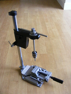
For other operations, such as number and letter stamping a rotating table is a useful addition to a pillar tool. Most workers have chosen to support such a table using a second arm on the pillar. Invariably the base of the table is then supported on the base of the pillar tool to provide more support. Why not build the table so that it mounts directly on the base plate? Doing this also means that the position of the table can be moved relative to the axis of the pillar tool. This would make it much better for stamping circular dials.
I have changed the spindle on my lathe for one with a 100mm flange (see here). As a consequence of this change I had two spare faceplates that would not fit the new spindle. The rotating table assembly was designed to utilise either of these faceplates.
I have changed the spindle on my lathe for one with a 100mm flange (see here). As a consequence of this change I had two spare faceplates that would not fit the new spindle. The rotating table assembly was designed to utilise either of these faceplates.
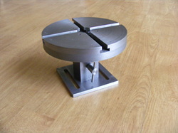
The rotating table was made by bolting a faceplate to a flanged spindle with a diameter of 25 mm. This spindle fits in a base that was bored out to be a close sliding fit to the spindle. The base is slotted for the mounting screws permitting its position to be altered relative to the pillar. A locking screw allows the table to be locked at any angular position.
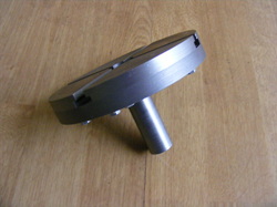
The faceplate bolted to a flanged spindle
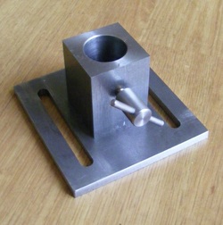
The base pillar is made from a 50 mm length of 38 mm square bar. This was faced off in a 4 jaw chuck and then bored out 25 mm to be a good sliding fit on the spindle. It was cross drilled and tapped M6 for the locking screw.
The locking screw was made from 12 mm round bar bored out and tapped M6 and then cross drilled 4mm to the lever. A length of M6 brass studding was then Loctited into the thread.
The base plate is 100mm square and was made from 6 mm steel plate. The plate is slotted with two 8 x 75 mm slots.
This is attached to the underside of the base pillar using four M5 countersink screws.
The base plate of the pillar stand was drilled and tapped M8 at two points either side of the central hole to match the spacing of the slots. The rotating table can then be bolted in position as shown in the header photo.
When used for number or letter stamping the sliding head is reversed on the pillar which allows the clamp to come very close to the surface to be stamped.
