Reduced height top slide
One of the problems with the standard cross slide is that it is too high. In the initial experiences page of this site (here) I noted that standard 1/4" carbide lathe tools were actually too high when mounted in the standard tool holder supplied with the lathe. When I made the QCTP, see here, I could only incorporate a step height of 2 mm to allow for variations in tool height. This is sufficient in most cases but , as always, there are exceptions. Some users overcome this by using a commercial QCTP where the toolholder hangs over the side of the top slide allowing much greater up and down movement. However, this style of toolpost is less rigid than a pillar type toolpost. The obvious answer to these problems was to lower the topslide. At the same time I decided to make two further modifications. The first was to incorporate a back lash adjustment into the topslide and secondly to make a new protractor that was more accurate.
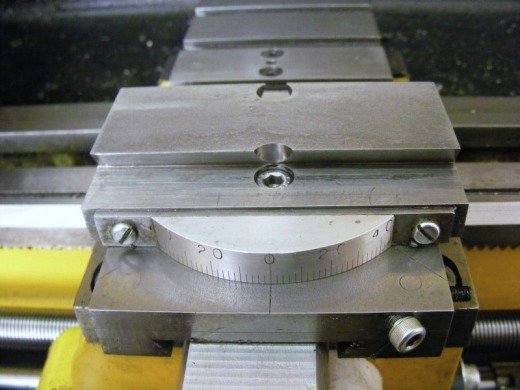
The new protractor was needed because the old one was too high to fit the new base and it is also not concentric with the pivot point of the cross slide. I had previously noted quite large errors (circa 2 degrees) with the old protractor at the extremes of the scale but it was only when doing this project that I realised that the protractor was not concentric with the pivot.
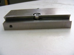
The photo above shows the new topslide base. It was machined from a piece of 16 mm x 50 mm cold rolled steel. This makes it 6 mm lower than the standard top slide base.
An 85 mm length of the steel bar was clamped exactly parallel to the y axis of the milling table and the two edges cut down to a depth of 6 mm. Then the dovetails were cut. The finished block was then drilled (from underneath) for the two clamping screws that hold the block to the cross slide. It was also drilled out to 8 mm longitudinally for the feed screw. The right hand end of this hole was opened out to 10 mm for a length of 20 mm.
The new protractor was needed because the old one was too high to fit the new base and it is also not concentric with the pivot point of the cross slide. I had previously noted quite large errors (circa 2 degrees) with the old protractor at the extremes of the scale but it was only when doing this project that I realised that the protractor was not concentric with the pivot.
The photo above shows the new topslide base. It was machined from a piece of 16 mm x 50 mm cold rolled steel. This makes it 6 mm lower than the standard top slide base.
An 85 mm length of the steel bar was clamped exactly parallel to the y axis of the milling table and the two edges cut down to a depth of 6 mm. Then the dovetails were cut. The finished block was then drilled (from underneath) for the two clamping screws that hold the block to the cross slide. It was also drilled out to 8 mm longitudinally for the feed screw. The right hand end of this hole was opened out to 10 mm for a length of 20 mm.
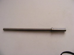
A new feed screw was made. This was actually a piece of M6 stainless steel studding. The end piece was turned and internally threaded and stuck to the end of the stud with epoxy resin. The reason for changing the feed screw was to allow room for a backlash adjuster on the feed screw nut. The feed screw may seem a little small but the topslide feed screw is mainly used in tension and even though it is slender it is unlikely to stretch. Compare this with the cross slide where the feed screw is used mainly in compression and here there is a possibility that the feed screw may bend and buckle. The only time the top slide screw is used in compression is when turning from the head stock towards the tailstock. In practice I have found no difficulty with either left hand or right hand turning using the M6 feed screw.
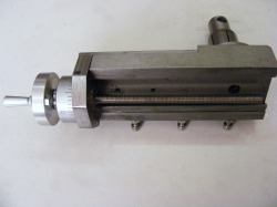
This shows the new feed screw assembled onto the top slide.
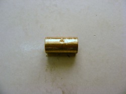
The feed screw nut is a piece of 10 mm phosphor bronze 20 mm long. It is threaded internally M6. At 10 mm from the end the nut is dimpled using the point of an M4 drill as shown in this photo.
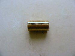
This photo of the feedscrew nut shows it rotated through 90 degrees. As can be seen the nut is slit along its length.
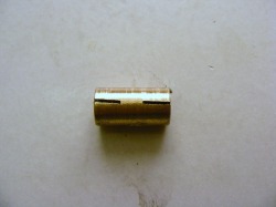
This photo shows the nut rotated through a further 180 degrees. This is also slit but from both ends leaving an unslit section in the middle.
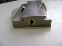
Here the feedscrew nut has been pressed into the 10 mm diameter recess in the topslide base. This is aligned so that the dimple is on the right hand side.
Note here the small M4 drilled and tapped hole on the left hand side of the photo. A socket head grub screw fits in here that bears on a bluntly pointed push rod that locates in the dimple on the feed screw nut. The push rod locates the nut in position and also as the grub screw is tightened then it compresses the nut closely into mesh with the feed screw.
A new protractor was made from a piece of 10 mm aluminium bar and graduated. The chord was carefully measured before cutting to ensure that the new protractor was concentric. This was attached to a piece of steel strip from the backside using two small M3 countersunk screws and then mounted to the front of the topslide base. The mounting holes were slotted so that the zero point could be accurately set against the line scribed on the cross slide.
The new modified reduced height topslide functions very well. It permits the use of an improved toolpost pillar, see here, it enables the backlash to be reduced to circa 2 divisions on the graduated collar ( the remaining backlash is that inherent in the ball bearing), the new protractor is more accurate and it is also much smoother due to the ball bearing.
The new modified reduced height topslide functions very well. It permits the use of an improved toolpost pillar, see here, it enables the backlash to be reduced to circa 2 divisions on the graduated collar ( the remaining backlash is that inherent in the ball bearing), the new protractor is more accurate and it is also much smoother due to the ball bearing.
