Rotary Broaching - the easy way.
Rotary broaching is a very useful way of producing hexagonal or other polygonal holes in metal. It can also be used to to produce internal splines and other profiles. It is especially useful for producing such profiles in short blind holes.
Commercial rotary broaching equipment is very expensive. Typically this can cost several hundred pounds. Furthermore, the shaped tools are all very expensive. A number of designs for rotary broaching tools have been published in magazines and on internet sources. These are tailstock mounted, quite complex and difficult to make.
The present project was embarked upon to develop a simple method of rotary broaching. The tool is very simple and has only two main parts. It is mounted on the cross slide. In addition, the tool is designed in such a way that it facilitates making the cutter. It uses the principle of using a hardened steel ball as a thrust bearing as in the Edgar Westbury rotating centre.
The principle of rotary broaching.
The principle of rotary broaching is quite straighforward. A hole is drilled in the workpiece with a diameter of slightly more than the minimum cross section diameter of the shape to be broached. With the workpiece rotating under power a shaped cutter that can freely rotate is brought up to the hole at a slight angle, typically around one degree, and it is pressed into the hole. The rotating workpiece causes the cutter to revolve and, because of the slight angle, the corners of the cutter come into contact in turn, each taking a peck as it does so. After one revolution the cutter has shaved a little metal from the hole, and as the tool is fed into the hole during subsequent revolutions, the hole is gradually broached to the shape of the cutter until the required depth is reached. In order to make any progress the cutter needs to have a draft angle slightly more than the inclination of the tool so that it does not jam. Typically this angle is around two degrees.
The tool.
The tool consist of two main components: the toolpost block and the cutter.
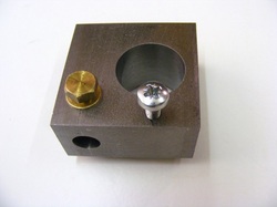
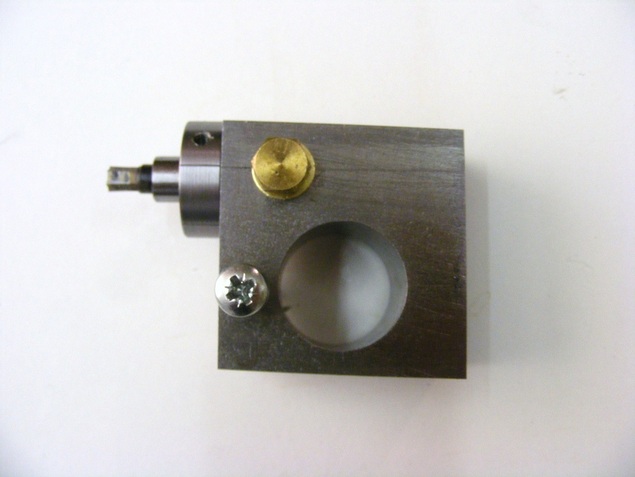
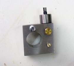
The toolpost block is designed to fit onto my toolpost. It is a block of steel 25 x 50 x 50 mm cut from a length of 25 x 50 mm bar. This was bored out with a 25 mm hole to fit over the toolpost. At right angles to the toolpost bore a 10 mm hole is drilled as shown on the front face of the block in the photo. A hole is also drilled and tapped M6 to accommodate the brass hex head screw. This screw can be used to lock a cutter blank in the 10 mm hole while it is being milled to shape (in use the tool is left free to rotate). Also shown in the photo is an M5 cross head screw. This passes right through the block and it is used to adjust the height of the tool on the tool post. Not obvious in the photo is that the block is not square. The front and back faces of the block are parallel but the sides are not. The left hand side of the block is angled at about one degree from the axis of the 10 mm hole and the right hand side is angled at about two degrees from the hole axis as shown in the following drawing.
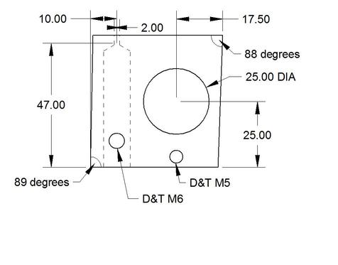
The one degree angled face is used for setting up the tool for broaching and the two degree angled face is used for actually making the cutter. Note the small 2 mm hole in the end of the 10 mm bore. This is to allow grease to escape when the tool is in use.
Note that my toolpost incorporates an expanding arrangement to grip the toolholder blocks. Those with more conventional posts will need to devise their own methods for securing the rotary broach toolholder. One approach might be a block that bolts directly down on the cross slide, the 10 mm hole in it having been made with a drill held in the lathe chuck to ensure that it is on centre height.
Note that my toolpost incorporates an expanding arrangement to grip the toolholder blocks. Those with more conventional posts will need to devise their own methods for securing the rotary broach toolholder. One approach might be a block that bolts directly down on the cross slide, the 10 mm hole in it having been made with a drill held in the lathe chuck to ensure that it is on centre height.
The cutter.
The cutter is made from a 65mm length of 10 mm diameter silver steel (drill rod in the USA). This should freely rotate in the 10 mm drilled hole in the toolpost block.
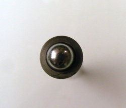
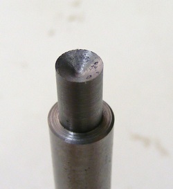
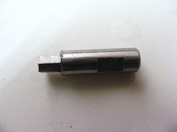
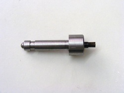
The length of silver steel is chucked in the lathe and faced. It is then centre drilled with a normal 60 degree centre drill such that a 6 mm hardened steel ball protrudes about half its diameter as shown in the photo.
The piece is turned around in the chuck and the other end faced. It is then centre drilled. A normal drill is then used to make a 118 degree depression in the end of the piece. The outside is then turned down to slightly greater than the maximum cross section diameter of the required profile. It has been turned down to 6 mm in the photo since the required cutter is for a 5 mm hexagonal hole.
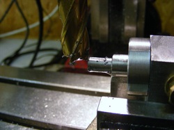
The prepared rod is then inserted in the toolpost block with the ball attached to the 60 degree conical hole using grease. An indexing ring is placed over the protruding part of the cutter as shown in the header photo, and then secured to the cutter with a grub screw. The indexing ring is simply an 8 mm wide collar, cross drilled and tapped for a 4 mm grub screw. The indexing ring is scribed at 60 degree intervals on the outside edge. The cutter is turned to line up one of the lines on the indexing ring with the fiducial mark on the block (see header photo) and then locked in the block with the brass screw. Set the block up in the milling vice lying on the two degree face and then using an end mill make a flat on the cutter. Loosen the brass clamp bolt and turn the cutter through 60 degrees using the indexing ring and relock in this position. Now mill the next flat. Repeat this operation until six flats have been milled. Check the cutter dimensions across the flats and readjust the mill z axis to give the final cutter dimensions and repeat the milling operations.
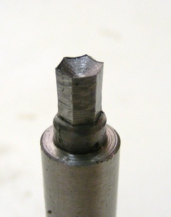
After milling the cutter should look like this. It should have an across the flats dimension of 5 mm at the tip with a two degree taper on each face becoming narrower the towards the base of the cutter.
The cutter is now ready for hardening and tempering. To harden the cutter warm it up with a torch and then dip in powdered soap until the soap adheres. Then heat it with a torch to bright red heat and quench in cold water. The soap limits oxidation and decarburisation of the steel. After quenching clean up the cutter shaft using very fine abrasive paper and polish the flats with a fine abrasive stone. Now heat the cutter gently with the torch until the flats are light straw and then re-quench. Clean the cutter shaft again with fine abrasive.
The cutter is now ready to use.
Grease the shaft of the cutter and the conical depression. Put the ball in place. Put a little grease in the 10 mm hole in the block and then push the cutter into the hole. Check that it rotates freely. The brass lock screw should be loose when broaching but it is best left in place to prevent ingress of dirt etc. Chuck a centre in the lathe chuck and place the broaching tool on the toolpost. Adjust the height of the cutter to centre it on the chucked centre. Remove the chucked centre and replace it with a piece of round bar. Line up the one degree edge of the block against the round bar. This sets the cutter at the correct angle. The broach is now set up and ready to use.
Chuck the work to be broached. Centre drill a small dimple and drill a hole to the minimum cross section diameter and to a depth greater than the required broached length. Wind the cross slide in to centre the broach over the hole, start the lathe at a fairly slow speed, lubricate the hole and the cutter, and then use the carriage handle to force the broach into the hole. It should go in fairly easily. If it is difficult then the hole size is probably too small. In this case withdraw the cutter and enlarge the hole slightly and try again. When the required broaching depth is attained, stop the lathe, and withdraw the carriage until the cutter is out of the toolpost block, taking care not to lose the ball. The cutter can then be "wiggled" out of the workpiece.
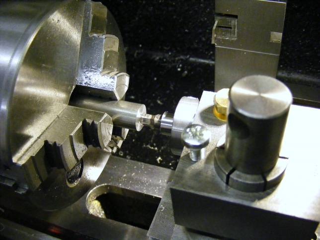
The photo below shows the set up for broaching:
Chuck the work to be broached. Centre drill a small dimple and drill a hole to the minimum cross section diameter and to a depth greater than the required broached length. Wind the cross slide in to centre the broach over the hole, start the lathe at a fairly slow speed, lubricate the hole and the cutter, and then use the carriage handle to force the broach into the hole. It should go in fairly easily. If it is difficult then the hole size is probably too small. In this case withdraw the cutter and enlarge the hole slightly and try again. When the required broaching depth is attained, stop the lathe, and withdraw the carriage until the cutter is out of the toolpost block, taking care not to lose the ball. The cutter can then be "wiggled" out of the workpiece.
The photo below shows the set up for broaching:
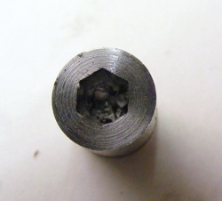
This shows the result of rotary broaching a piece of 10 mm steel with a 5 mm AF hexagonal cutter. The material shaved from the hole is the compacted matter at the bottom of the hole.
The tool is not limited to hexagonal shapes. With a different indexing ring other polygonal shapes can be easily made. Indeed other profile cutters, e.g. fine splines could be made.
The tool is not limited to hexagonal shapes. With a different indexing ring other polygonal shapes can be easily made. Indeed other profile cutters, e.g. fine splines could be made.
As the cutter size increases then the force required to broach the hole increases. One way to assist this process is to use the tailstock to push the carriage forward. The insertion force is very dependent on the hole size. Slightly too small a hole will give a very high insertion force. It is much easier if the hole is slightly too large. Making a conical lead-in to the hole by using a countersink bit makes it easier to align the tool with the hole. The lead-in can be machined away afterwards if necessary.
My thanks to Andrew Franks for making some helpful suggestions and advice regarding the text.
Improved cutter holder
The design presented above works very well but each cutter is a large piece of silver steel. A new cutter holder has been designed to hold a much smaller cutter.
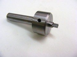
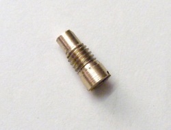
The new cutter holder is made from one piece of 25 mm bar. It was machined down to 10 mm for most of its length as shown to fit in the bore of the toolpost block. The rear end of the 10 mm shaft is drilled with a BS4 centre drill for the ball. The wide end is drilled out to 6 mm for a depth of 14 mm for the cutter which is held by an M4 grubscrew. The large end was divided to give six equally spaced graduations for indexing.
This whole unit replaces the cutter in the original design.
This whole unit replaces the cutter in the original design.
The new cutters are made from 6 mm diameter silver steel and they are 24 mm long. A flat is milled on the shaft of the cutter as shown in the photo. This flat is for the grubscrew to lock the tool in the holder and prevent any rotation during milling of the cutter profile.
After profiling the cutter is hardened and tempered as before.
After profiling the cutter is hardened and tempered as before.
The new cutter holder works very well and is much more economical with expensive silver steel.
Modification for tool withdrawal under power.
The tool as first designed broaches very well. However, after broaching the cutter had to be manually removed from the workpiece by wiggling and pulling. The tool has now been modifed to enable the cutter to be withdrawn whilst the cutter is rotating. This makes removal of the cutter much easier.
The toolpost block has been modified by adding an additional brass screw. This is visible below the large brass hexagon lock screw at the top of the photo.
The block was drilled 4 mm for the screw and then opened out for 6 mm to 4.3 mm and this portion tapped M5.
The block was drilled 4 mm for the screw and then opened out for 6 mm to 4.3 mm and this portion tapped M5.
The cutter holder shaft has been modified. A groove 1 mm deep and 5 mm wide has been turned about 8 mm from the end.
The section of the cutter holder on the right hand side has been reduced in diameter from 25 mm down to 20 mm diameter and re scribed with six equally spaced graduations. The reason for this is that the cutter holder will be captive in the block after the modification and the 25 mm diameter would have prevented the 1 degree edge of the block from being lined up with the lathe axis.
The section of the cutter holder on the right hand side has been reduced in diameter from 25 mm down to 20 mm diameter and re scribed with six equally spaced graduations. The reason for this is that the cutter holder will be captive in the block after the modification and the 25 mm diameter would have prevented the 1 degree edge of the block from being lined up with the lathe axis.
The M5 brass screw is turned down to 4 mm at the end. When this is screwed into the toolpost block it protrudes into the spindle bore and engages with the groove in the cutter holder shaft. The protruding length is adjusted by filing so that the it engages with the groove but does not bear on and lock the shaft when the screw is tightened down.
Video of the tool in action.
To watch a video of the tool in action click here.
Rotary broaching on the mill.
Rotary broaching can be very simply carried out on the mill once the cutters have been made as shown here.
