Rotary table tailstock.
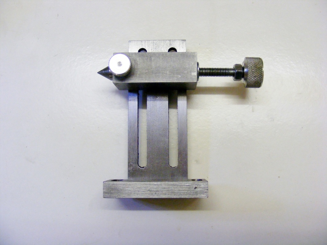
This tailstock was designed for use with my rotary table. This has a centre height of 85 mm. I have made the height fully adjustable from 20 mm to 90 mm since it may be useful as a tailstock for other uses.
It comprises several main components. There is a base attached to a slotted upright piece. To the upright is attached a block which carries a 60 degree centre. This centre can be extended by a turning the knurled adjustment screw on the right. It can be locked in place using the smaller knurled knob on the block or by using the locknut on the adjuster screw.
The base was made from a piece of 10 x 25 x 60 mm steel.
The upright was made from a piece of 6 x 40 mm steel 100 mm long. This was slotted with two 6mm slots that are 20 mm apart. The slots extend from 20 mm at the base end to 91 mm at the top end.
The block is a piece of 19 x 25 mm steel 50 mm long. This was drilled through axially with a 5 mm drill. It was then counterbored 10 mm for a length of 30 mm. The 5 mm section of the bore was tapped M6.
The upright was attached to the base using two M4 socket head screws.
The block was attached to the upright using two M5 screws. These screws pass through a plate, 1.5 mm x 10 mm, then through the slotted upright and then into M5 tapped holes in the block.
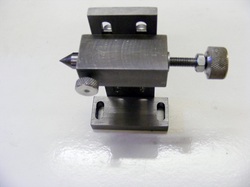
The height of the block can be easily adjusted by loosening the screws and sliding the block into alignment with the work.
The block was attached to the upright using two M5 screws. These screws pass through a plate, 1.5 mm x 10 mm, then through the slotted upright and then into M5 tapped holes in the block.
The height of the block can be easily adjusted by loosening the screws and sliding the block into alignment with the work.
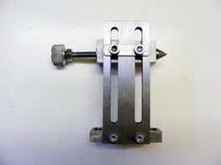
The base is slotted to facilitate alignment of the tailstock with the work mounted on the rotary table.
The back knurled screw is M6. The knurled knob was made from aluminium and then fixed in place with epoxy resin. Turning this knob clockwise pushes the centre out of the block.
The back knurled screw is M6. The knurled knob was made from aluminium and then fixed in place with epoxy resin. Turning this knob clockwise pushes the centre out of the block.
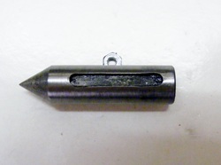
The centre was made from 10 mm silver steel (drill rod in US) 45 mm long. The end was turned to a 60 degree point. A 3mm groove was cut along its length as shown.
The front knurled M3 screw engages in this groove. This stops the centre rotating, provides a means of locking the centre in position and stops the centre sliding out of the block.
The centre was hardened by heating to red heat and then quenching in water. It was re-polished and then tempered to light straw.
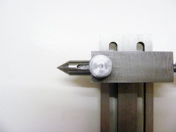
This photo shows the centre with groove lined up under the front screw.
