Rotary tool stand.
I often use my rotary tool for cutting HSS steel lathe tool blanks. Doing this freehand is tedious and not very accurate. In fact many times I just use the rotary tool to groove the blank and then just snap it and clean up the ends with the bench grinder.
A posting on the HMEM group by Mklotz (http://homemodelenginemachinist.com/index.php?topic=414.0) descibed a simple jig to hold a Dremel tool. A small table was attached to part of the jig to enable work to be supported during cutting. The table could be tilted for angular cuts. This seemed a very much better way of cutting tool steel compared with the free hand method. The author described a number of other attachments for the jig.
The jig described here is very much a copy of the Mklotz design but it differs in detail.
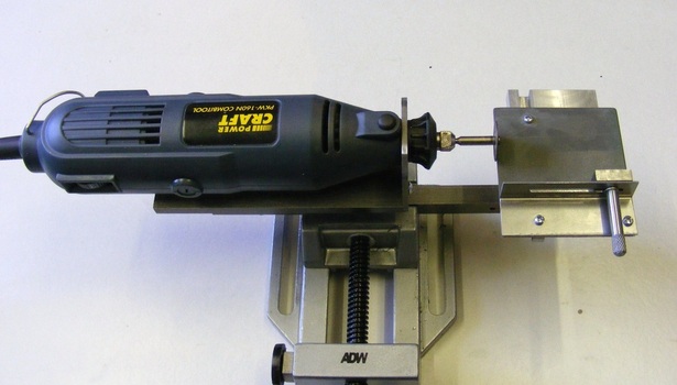
My rotary tool is a cheap Chinese import that was purchased from Aldi. The black plastic collar on the left hand side unscrews. The tool can be clamped by passing the screwed section through a suitable hole and then screwing the black plastic collar back in place.
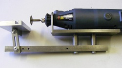
The rotary tool sits on a base plate of 50 x 6 mm steel about 120 mm long. At the left hand end is a piece of 50 x 3 mm steel bolted at right angles to the base plate using M4 screws. The plate has a 18 mm hole drilled through it. The nose of the rotary tool passes through this plate and it is secured in place using the threaded black collar. The base plate is attached to a 12 mm square bar using M5 screws and two 12 mm round spacers. The spacers are 25 mm long. At the left hand end of the square bar is the table.
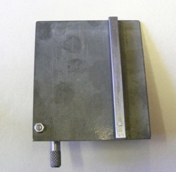
The table is made from 50 x 10 mm aluminium bar 80 mm in length. A short length of 12 square bar is attached to the underside of the table using M4 countersunk screws. The table is linked to the lower bar by a slotted link. This combination allows the table to be both tilted and adjusted for height.
Note that there are several M4 tapped holes below the table. This allows the table to be repositioned in different places as required.
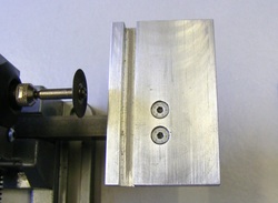
A slot is milled in the top surface of the table. The slot is 6 mm from the edge, 6 mm wide and 6.5 mm deep.
Note the two countersunk screws. These secure the 12mm square bar to the underside of the table.
Note the two countersunk screws. These secure the 12mm square bar to the underside of the table.
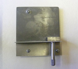
The table accepts a sliding component that is made from 1 mm thick steel sheet. The M3 screw at the top and the one immediately below it secure a 6 mm square bar to the underside. This fits into the slot in the table.
At the bottom is a right angle bracket. This has a 3mm slot along its length (see header photo). The knurled rod terminates in a section which is turned down and threaded M3. This passes through the slot and screws into the stop block shown on the lower right hand side.
At the bottom is a right angle bracket. This has a 3mm slot along its length (see header photo). The knurled rod terminates in a section which is turned down and threaded M3. This passes through the slot and screws into the stop block shown on the lower right hand side.
This shows the underside of the sheet with the 6 mm bar attached.
The nut at the bottom left secures the right angle bracket.
The slider overhangs the table on both sides. Being thin the slider can be positioned very close to the the cutting disc even when the table is angled.
The nut at the bottom left secures the right angle bracket.
The slider overhangs the table on both sides. Being thin the slider can be positioned very close to the the cutting disc even when the table is angled.
This very simple stand was made from mostly scrap materials and it is capable of making accurately square cuts in tool steel. In use the stand is held in the bench vice and the item being cut is held, with a finger, against the angle plate and the stop block. The slider then advanced into the cutting disc. The only problem with this is that the item being cut gets very hot, too hot to hold with a finger, and it is necessary to stop frequently to allow it to cool. Some sort of clamp is required to solve this problem.
