Speed reducer.
The speed controller on the minilathe is very versatile. On my lathe, as supplied the motor speed could be varied from practically 0 to 2500 rpm. Whilst the speed range is very good the torque available at low speed is low, even in the low gear. This does not matter for turning small components (<50 mm diameter) because reasonable spindle speed can be used. However, when turning targe diameter components then the lack of torque at low speeds means that only very shallow cuts can be taken. Another problem with slow speed running is that the motor tends to overheat. The cooling fan is built into the motor and runs at the same speed as the motor so at low speeds there is too little motor ventilation. On my lathe I hardly ever used the high speed range so in order to increase the low speed torque and improve the motor ventilation I decided to reduce the spindle speed by about half.
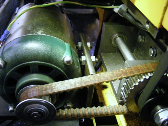
The photo above shows the arrangement used to achieve this. It is based very much on the general ideas used by Ralph Patterson for his speed reducer and detailed drawings of his implementation are on the ToolsandMods website (www.toolsandmods.com). The motor is removed from the cavity under the lathe bed and this is replaced by by a bracket carrying a small layshaft running in 608zz ball bearings. On the end of the layshaft are mounted two timing belt pulleys. The outer pulley is the original motor pulley that connects up to the spindle gears via the original timing belt. The inner pulley is a 35 tooth T5 timing belt pulley that connects to a 16 tooth T5 pulley mounted on the motor shaft. This gives a 2.2 reduction ratio.
The photo above shows the arrangement used to achieve this. It is based very much on the general ideas used by Ralph Patterson for his speed reducer and detailed drawings of his implementation are on the ToolsandMods website (www.toolsandmods.com). The motor is removed from the cavity under the lathe bed and this is replaced by by a bracket carrying a small layshaft running in 608zz ball bearings. On the end of the layshaft are mounted two timing belt pulleys. The outer pulley is the original motor pulley that connects up to the spindle gears via the original timing belt. The inner pulley is a 35 tooth T5 timing belt pulley that connects to a 16 tooth T5 pulley mounted on the motor shaft. This gives a 2.2 reduction ratio.
This shows more details of the layshaft bracket. It was made from a piece of 50 mm x 50 mm x 6 mm angle. Two end plates, 10 mm thick, were bolted to the angle. The end plates are recessed to carry the two pressed in 608zz bearings. The layshaft was machined from 10 mm round steel. This was machined down at both ends to 8 mm to fit the bearings. A keyway was milled in the protruding end of the shaft for the two pulleys.
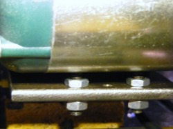
The motor is supported on the cantilevered bar that fits between the monting blocks and the lathe casting, as described in the section entitled Mounting, drip tray and chip guard. The cantilevered bar has a 6 mm slot machined along the center line. The motor bracket is bolted through this slot to the bar. The slot enables the motor to be slid along the bar to adjust the belt tension. The motor bracket is made from 2.1/2" x 2.1/2" x 1/4" angle
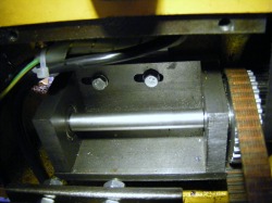
This photo shows the motor mounted to motor bracket. The studs that screw into the motor are the same as those originally used to mount the motor under the lathe bed. The double nuts on each stud enable the angle of the motor to be adjusted to set the tracking of the belt.
Setting up the tracking of the belts is tricky. First adjust the layshaft bracket position to get the belt to the spindle gearing tracking properly. Once this belt is tracking properly then adjust the motor position and angle until the T5 belt track well.
A new cover was made to enclose the motor, pulley and belt system to keep swarf from entering.
A new cover was made to enclose the motor, pulley and belt system to keep swarf from entering.
