Tailstock modifications
The standard Sieg tailstock on my Clarke lathe has many annoying features:
1. The scale on the tailstock barrel is very faintly etched and it is calibrated in imperial units. I usually work in metric units so this is inconvenient.
2. The tailstock is locked to the lathe bed with a spanner. My spanners always seem to disappear when I need them!
3. The base and the upper part are separate to allow the angle of the tailstock and the position of the tailstock to be adjusted and aligned with the headstock. However, the lock nut to fix the position and angle is underneath the tailstock. In removing the tailstock to lock these settings, the adjustments are disturbed. This make setting up the tailstock alignment difficult.
4. Adjustment of the alignment is carried out by physically moving the upper part relative to the lower part by tapping with a hammer. There is no precise, reproducible way of moving the tailstock to get alignment.
5. There is no micrometer collar on the feed screw hand wheel for precise depth control.
6. The base of the tailstock is quite small circa 2.5 "wide
7. The clamping plate under the tailstock is quite small and crudely made.
Real Bull have introduced a much better tailstock on some of their lathes. This is wider (circa 4") and includes a lever lock. The barrel is much more substantial and very clearly engraved in both metric and imperial units. However the base is much more bulky and this gets in the way for some operations unless the barrel is greatly extended.
Addressing the issues.
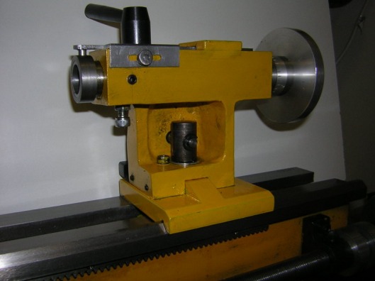
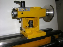
A scale has been added to the top of the tailstock. This scale was part of a very cheap imported vernier caliper which was cut down. It is clearly engraved in both imperial and metric units.The front end of the scale is attached to a collar on the tailstock barrel. The collar is held to the barrel with a small grub screw. The scale rides on top of the tailstock and is located at the other end by a recessed steel block. It is a sliding fit under the block. On the edge of the tailstock is a piece of aluminium angle with a line against which the scale can be read. The aluminium angle is retained in position by a knurled screw, also recovered from the cheap caliper. The angle is slotted so that the scale can be moved to line up with the zero mark on the scale.
The clamping nut has been replaced by a cam lock. The design of this is based very much on that described by John Moran (www.gadgetbuilder.com) so no further explanation is required here. This photo also shows the tailstock locking screw just to the left of the cam lock. This has beeen located to the top side of the tailstock rather than underneath. This was very easy to do. It is only necessary to drill a hole through the upper casting and make a square nut to fit the recess in the bottom casting. Now it is possible to align the tailstock and just lock it into position without having to remove the tailstock from the lathe bed. This photo also shows the graduated collar that has been added to the tailstock feed handle.
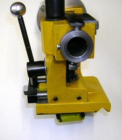
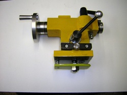
Just above the bottom casting on the front of the tailstock two grubscrews have been added. These bear on brass pads that press against the raised part of the bottom casting. These permit the angular alignment of the tailstock.
On the left is the cam lock lever and below that is an adjuster that allows the horizontal position of the tailstock to be set.
On the left is the cam lock lever and below that is an adjuster that allows the horizontal position of the tailstock to be set.
Another grub screw just below the aluminium angle. This screw, which also operates on a small brass pad can be adjusted to remove any side play in the tailstock barrel. Up and down play can be eliminated using the standard screw under the tailstock.
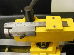
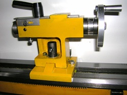
This photo shows the back of the tailstock. An adjuster bar has been added at the bottom of the tailstock with an adjuster screw that is used to align the the tailstock barrel with the headstock. This modification is published on the Littlemachineshop website (www.littlemachineshop.com) so no further discussion is needed here. Also shown in this photo is the cam lock lever. Note the small rod protruding from the camlock hub and the small adjustable stop. This prevents the lever flopping forward when the cam lock is not locked. Note also that a new base has been made to replace the normal base casting. This was machined from hot rolled mild steel. It is wider than the normal casting to provide a sturdier base. Part of the reason for replacing this was that the quality of the machined surfaces on the as supplied base casting were very bad (perhaps machined with a chainsaw!). To go with this an extended locking plate was made and this is connected to the cam lock as shown but there is also a hex head screw at the handle end of the tailstock that attaches to the locking plate. This stops the locking plate turning and this makes taking the tailstock on and off the lathe bed much easier.
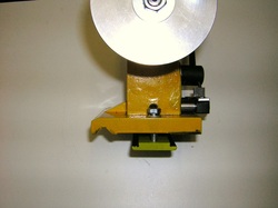
This photo shows some detail of both the new base plate and the cam lock locking plate. The vee groove was milled using a 90 degree contersink after first miiling a 4mm groove. The locking plate is stepped on either side so that it locates in the gap between the two ways. The hex head anti-rotation screw is visible directly under the tailstock handwheel. Normally this is left loose but it can also be used to provide extra clamping if required.
With all these modifications the tailstock is much easier to align and use.
At a later date I also added a lever feed to the tailstock, see here.
At a later date I also added a lever feed to the tailstock, see here.
