Tee slot cross slide.
Tee slotted cross slides are normal on up market lathes. In addition to allowing workpieces to be bolted to the cross slide for in line boring or other machining it is also useful for mounting other items to the cross slide such as a rear tool post, a coolant nozzle or a chip/coolant shield.
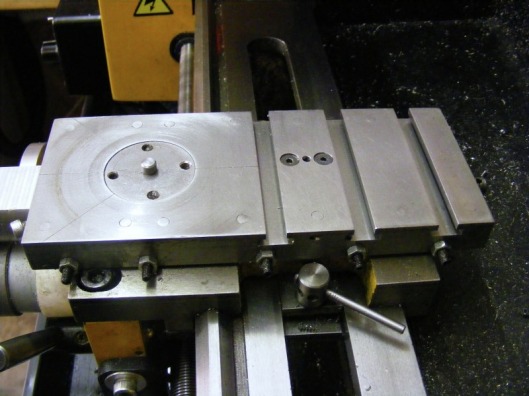
This cross slide was designed so that it was longer (180 mm) and wider (75 mm) than the standard cross slide and to incorporate a number of other features. The first of these is a better method of adjusting the angle of the top slide and the second to have tee slots at the rear of the cross slide. A number of other small improvements were added such as the top face has three index lines at 45 degrees to each other as can be seen in the above photo, and it has more gib screws. Having three index lines at 45 degrees to each other allows the protractor to be used over the range +/- 90 degrees whereas the standard arrangement with one line limits the protractor use to +/- 45 degrees.
The disc in the centre of the front plate is the top slide turn table. This has a circular dovetail that mates with a similar dovetail in the top plate. There are three brass gib rods, that centre the disc in the plate, at 120 degrees to each other. The gibs are adjusted with M4 screws. Tightening any of the gib screws locks the plate in position.
I did contemplate a cross slide with tee slots covering the whole of the cross slide upper surface and then making the top slide as a separate unit that would bolt onto the tee slots. However, this approach does not work well because of space restrictions.
The laminated method of construction is due to Martin Cleeve and it was first published 50 years ago.
This photo shows the front of the cross slide and the laminated construction. The middle layer is the base plate which is made of 1/8" x 3" steel. The top layer is constucted from 1/4" x 3" steel. At the bottom are the two dovetails. The dovetails were cut on the milling machine from a piece of cold rolled 1/4" x 3" steel using a slitting saw and taking repeated small cuts along the length of the steel held at a 60 degree angle. This method was adopted because my angle vice is only 75 mm wide and with the steel held in the middle the forces using a conventional milling approach would have caused deflection of the steel and inaccurate dovetails at the extreme ends. It was interesting that the first dovetail cut was from the edge of the steel and these were completely banana shaped due to the relaxation of the surface stresses in the steel. This had to be discarded. Subsequent dovetails cut from the middle of the sheet were straight. The gib strip was cut in the same way
The M4 screw protruding from the front is for locking the top slide turntable.
The M4 screw protruding from the front is for locking the top slide turntable.
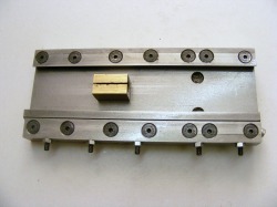
This shows the underside of the cross slide. The base plate, dovetails, turntable plate and the tee slots are all held together by M5 screws. Note also the split brass nut for the feed screw. The standard brass nut wears slowly introducing back lash. With the split nut when the nut wears it can be squeezed together a little to restore the fit.
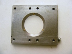
This shows the underside of the front top plate removed from the cross slide. Note the three brass gib rods. These are operated by M4 screws. These are grub screws at the 8 and 12 o'clock positions but the screw at 4 o'clock emerges from the plate and is accessible from the front of the cross slide. This screw is the one used for locking the turntable.
The circular dovetail is machined at 60 degrees.
The circular dovetail is machined at 60 degrees.
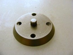
This shows the top slide turntable. The dovetail angle is 60 degrees to match the top plate above. The thickness of this component (6 mm) is slightly less than the thickness of the top plate (1/4" = 6.4 mm) so that as the gib rods are tightened then the turntable is pulled down into the top plate clamping the top slide firmly to the top plate.
Note that there are 4 holes in this unit. Only two are necessary to bolt the topslide to the turntable. As I originally designed the cross slide I intended to bolt the top slide to the turntable from underneath the cross slide into threaded holes in the topslide. This did not work well because it was very difficult to take the topslide on and off the turntable so I subsequently modified it so that the top slide bolted onto the turntable from above into threaded holes in the turntable.
Note that there are 4 holes in this unit. Only two are necessary to bolt the topslide to the turntable. As I originally designed the cross slide I intended to bolt the top slide to the turntable from underneath the cross slide into threaded holes in the topslide. This did not work well because it was very difficult to take the topslide on and off the turntable so I subsequently modified it so that the top slide bolted onto the turntable from above into threaded holes in the turntable.
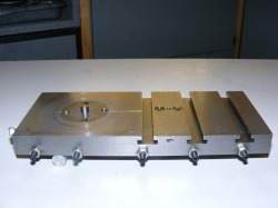
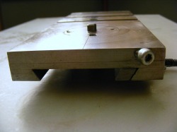
This is a side view of the cross slide. The tee slot pieces are made from 1/4" x 1" steel with a 3 mm x 3 mm section milled from both edges. Note the small angled hole between the third and fourth gib screws. This provides access to one of the turntable gib screws.
The gap between the tee slots is 8 mm.
This project was fairly straightforward. The most difficult part was getting all the components lined up for drilling the holes for the screws that hold everything together. To do this the top plate and tee slot bars were marked out with the screw holes and drilled 4.3 mm. The non gib side of the base plate and dovetail were marked out and drilled 5 mm. The non gib side of the top plate and tee bars were tapped M5 and then one side of the cross slide assembled. This was placed on the lathe carriage and the gib placed and then the other dove tail. Holding this all down and with the gib pushed in then the base plate was spotted through the top components. The base plate holes where drilled 4.3mm and the whole reassembled on the carriage and the holes were spotted through to the dovetail. This was drilled. The top components were then tapped M5 and the base plate and tee dovetail drilled out to 5 mm. The dovetail holes were then countersunk. All holes were deburred and everything cleaned up before final assembly.
If I were to remake the cross slide I would alter the positions of the screws on the gib side so that the gib screws could be placed equally spaced along the cross slide.
If I were to remake the cross slide I would alter the positions of the screws on the gib side so that the gib screws could be placed equally spaced along the cross slide.
Acetal leadscrew nut.
The brass nut under the cross slide wears slowly over time and periodically it is necessary to squeeze the split nut in order to reduce the backlash. This involves some dismantling and it is not a quick operation.
For some time I contemplated changing the brass nut for an acetal (Delrin) nut. These are commonly used on CNC machines because they have low friction, wear slowly and can give almost zero backlash. The big problem with fitting an acetal nut to replace the brass nut is the small M4 screws that attach the nut to the underside of the cross slide. These screws only screw into the brass nut about 3 mm. This is sufficient to hold the brass nut in place securely but I could envisage the screws being pulled out of the much weaker acetal material if the cross slide was heavily stressed during use. The channel in which the nut moves is quite narrow and there was no room to provide better or more numerous fixings.
In a lightbulb moment I had the idea to extend the back of the cross slide a little and attach the acetal nut using long screws to this extension. The cross slide feedscrew would need to be extended to compensate for the extra reach required.
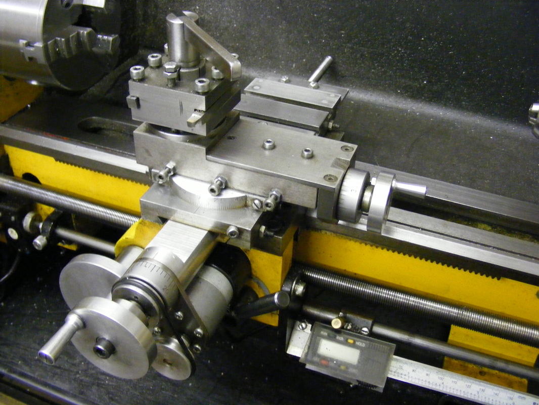
The photo above shows the cross slide after installing the acetal nut. Note the much longer leadscrew extending out of the back of cross slide.
For some time I contemplated changing the brass nut for an acetal (Delrin) nut. These are commonly used on CNC machines because they have low friction, wear slowly and can give almost zero backlash. The big problem with fitting an acetal nut to replace the brass nut is the small M4 screws that attach the nut to the underside of the cross slide. These screws only screw into the brass nut about 3 mm. This is sufficient to hold the brass nut in place securely but I could envisage the screws being pulled out of the much weaker acetal material if the cross slide was heavily stressed during use. The channel in which the nut moves is quite narrow and there was no room to provide better or more numerous fixings.
In a lightbulb moment I had the idea to extend the back of the cross slide a little and attach the acetal nut using long screws to this extension. The cross slide feedscrew would need to be extended to compensate for the extra reach required.
The photo above shows the cross slide after installing the acetal nut. Note the much longer leadscrew extending out of the back of cross slide.
|
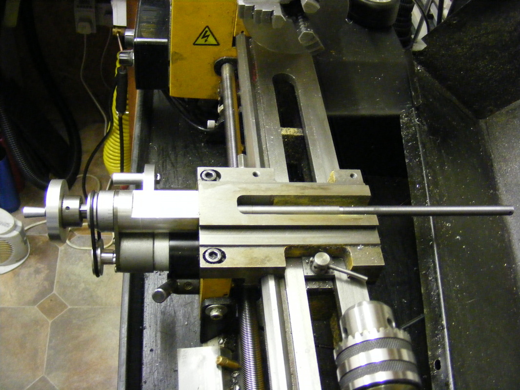
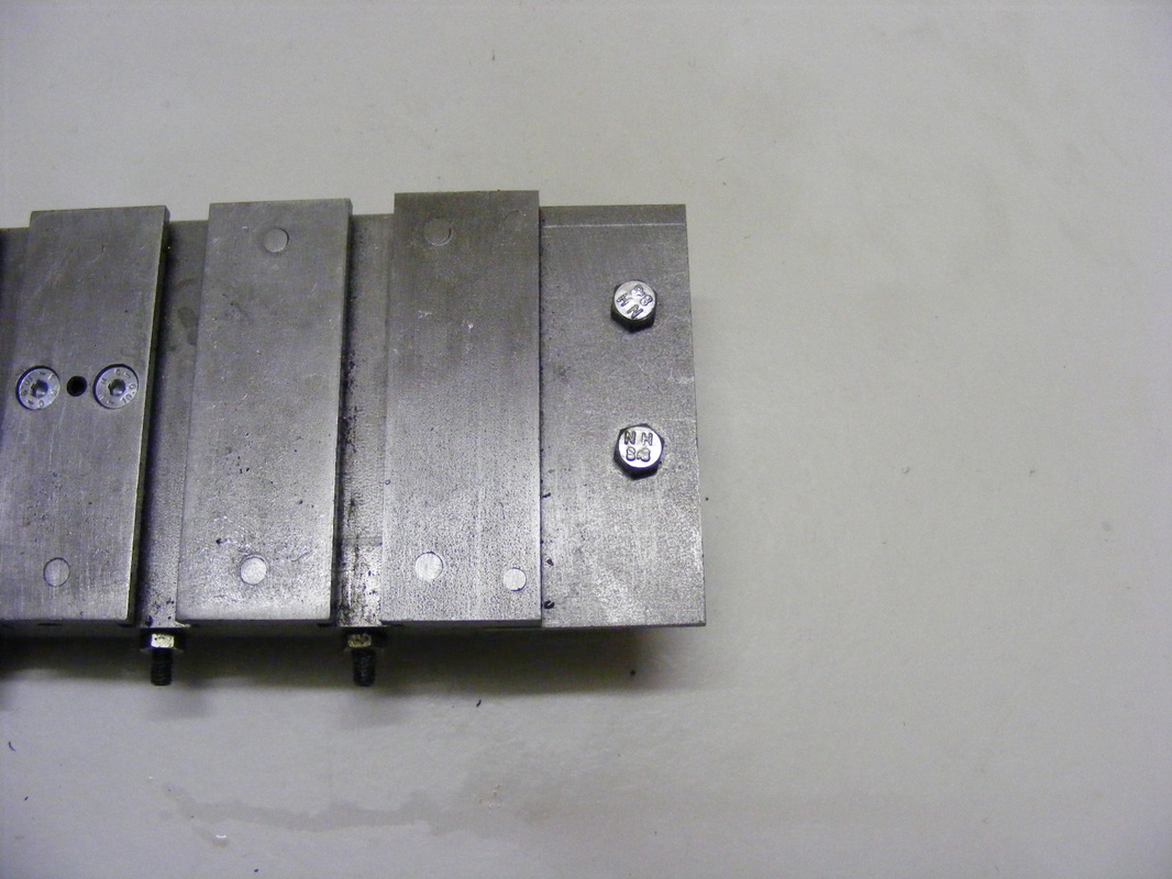
This photo shows the new longer feedscrew installed in the cross slide base.
This was made from a length of 10 mm diameter free cutting steel (EN1A). One end was turned down to 8 mm and then drilled and threaded M6 as described here. The other end was single point threaded at a 1 mm pitch using a 60 degree threading tool. for a length of about 140 mm. The total length of the new feedscrew was 360 mm |
|
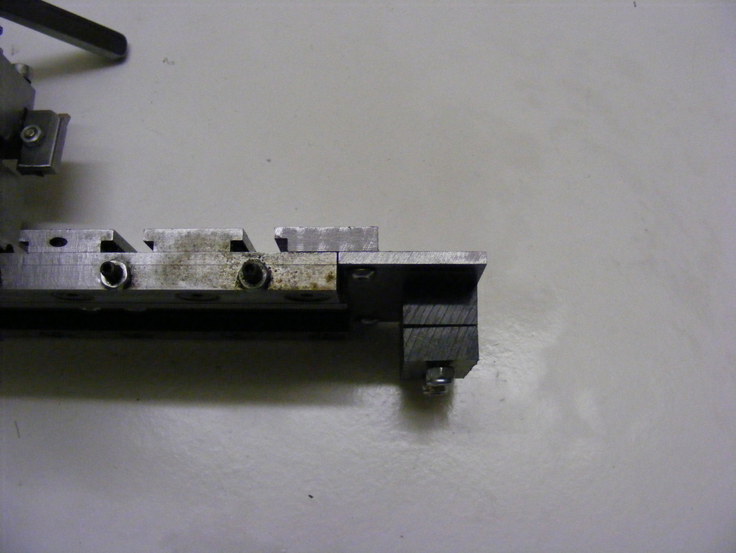
The narrow rear tee slot piece at the end of the cross slide was removed and replaced by a new one made from 1" x 1/4" mild steel. This was milled out on one edge 3 mm wide and 3 mm deep to form the tee slot, as described above. It was attached to the cross slide using M5 counter- sunk screws from the underside.
A piece of 36 mm wide 3 mm thick steel was attached to the over hanging tee slot piece using M4 button head screws. The two hex head screws on the top of this plate secure the acetal nut in position. |
|
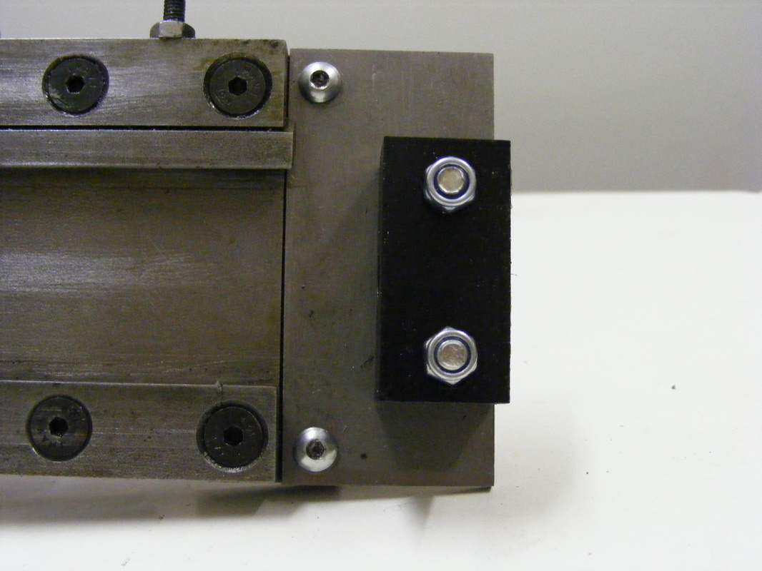
This shows a side view of the changes to the back of the cross slide. The new wider tee slot piece is attached to the cross slide and the 3 mm plate is attached to it.
The black blocks on the right are the acetal feedscrew nut. |
|
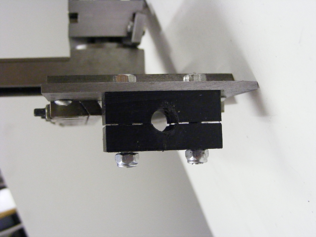
The large black countersunk screws at the end of the dovetails secure the tee slot piece to the cross slide.
The two button heads secure the 3 mm extension plate. The two nuts on the acetal blocks are adjustment screws |
|
The acetal nut was made from a block of acetal 40 x 21 x 20 mm. The 40 x 21 mm face was drilled in the centre with a 9 mm drill and then tapped with a 10 x 1 mm left hand tap.
The 40 x 20 mm face was drilled with two 4.3 mm holes positioned equally either side of the 10 mm tapped hole and spaced 25 mm apart. These holes were tapped M5. The nut was then slit into two pieces using a 1.5 mm slitting saw. The top piece is 10.5 mm thick |
and the bottom piece is 9 mm thick. The holes in the bottom piece were drilled out to 5 mm so that it slides on the 30 mm x M5 screws that secure the top part to the 3 mm extension plate. The bottom part was loosely held in place using M5 locknut.
The cross slide was then slid onto the saddle casting and the feedscrew engaged into the acetal nut. The lock nuts were tightened down until the two halves of the acetal nut closed around the feedscrew. The nuts are tightened down hard enough to eliminate the backlash but not so hard that is difficult to turn the feedscrew.
This acetal nut modification was relatively easy to do and experience so far is that backlash can be set to practically zero. If and when the nut wears it is a simple job to tighten the lock nuts to reset the backlash to zero. This can be done without dismantling anything.
