Tee slot faceplate
There is nothing wrong with the standard Sieg faceplate for holding large objects. However, for holding small irregularly shaped objects the bolt holes for the clamping screws are too far out for the clamps to reach the centre. This is because the design is limited by the spindle flange which prevents the clamp bolt holes from being positioned closer to the centre. One way around this is to drill and tap holes closer to the centre for clamp bolts but every faceplate job tends to be different and such holes are never in the right place for the next job so you have to drill and tap more holes.
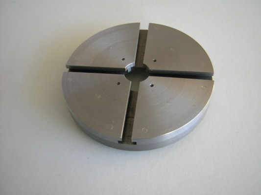
A more elegant solution is to use a tee slotted faceplate where the clamping bolts can approach very close to the centre. The faceplate described here is of laminated construction comprising three layers.
A more elegant solution is to use a tee slotted faceplate where the clamping bolts can approach very close to the centre. The faceplate described here is of laminated construction comprising three layers.
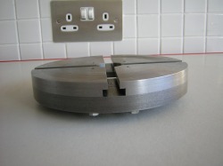
This photo shows the edge of the faceplate and the three layers. The lowest layer is clearly visible. This is the cast iron base plate. It was machined from a dumb-bell weight. The back of this plate has a register recess machined in it to match the register on the spindle. The next layer consists of 4 quadrants of 5 mm hot rolled steel each separated by a gap of 14 mm. The final layer is another four quadrants of the same steel but separated by a gap of only 8 mm. The whole assembly is bolted together with M5 bolts passing through the cast iron base plate, through the first steel layer and into tapped holes in the final layer of steel. As can be seen this form of construction automatically forms the tee slots. The tee slots match the tee slots on my milling machine so that the clamps used are interchangable for the two machines.
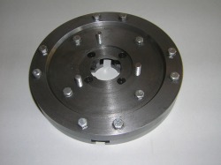
This photo shows the back of the faceplate with the spindle register and the mounting studs. The hex head screws holding the assembly together are also clearly visible.
To make the unit the base plate is first prepared by turning down the cast iron plate, cutting the register and then drilling and tapping the stud holes. The steel quadrants start off as right triangles of 5 mm hot rolled plate. Eight of these are required. Pairs of these are laid on the baseplate and carefully positioned and then clamped into place. 3mm pilot holes are then drilled through the cast iron and through the assembly.The holes in the cast iron and the first steel layer are opened out to 5 mm and those in the top layer are drilled and tapped M5. This is repeated with the three other pairs of triangles. Once all the parts of the assembly are bolted down the M5 screws are trimmed close to the surface of the top.
Excess material where the triangular pieces overlap the edges of the base plate is then roughly trimmed away with a hacksaw and the assembly mounted on the lathe spindle. The edge of the assembly is turned to smooth the edges of the top layers back to the base plate diameter. The cente of the face plate is then bored out to the spindle bore (20 mm) with a boring tool. Finally the surface of the base plate is faced to level the protruding screws and remove the mill scale from the top layer.
