Update on gear cutters.
My method for making gear cutters using the cone drill is as follows:
1. Make a centre line along the length of the cutter blank.
2. Mount the blank in the vice.
3. Centre the blank under the cone drill in the milling machine by lining up the tip with the centre line. Set the feed screw dial to zero.
4. Use the cone drill to mill the front edge of the blank to the correct angle.
5. Return the cone mill to the centre of the blank and traverse the cutter to the right by 1/2 the button spacing and then fix a stop on the mill table at this point. Lock the table and reset the feedscrew dial to zero.
6. Traverse the table the full button spacing to the left and set another stop at this point.
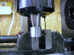
7. Move the blank to the mid position and set the cone drill height to the required level. Lock the quill.
8. Advance the blank into the cone mill until it just starts to cut.
9. Set the infeed dial to zero.
10 move to the left hand stop. Lock the table and advance the blank by the required infeed.
11. Return the table to zero infeed and move to the right hand side, lock the table and advance by the required infeed again.
This sequence of operations takes only about 15 minutes to complete.
1. Make a centre line along the length of the cutter blank.
2. Mount the blank in the vice.
3. Centre the blank under the cone drill in the milling machine by lining up the tip with the centre line. Set the feed screw dial to zero.
4. Use the cone drill to mill the front edge of the blank to the correct angle.
5. Return the cone mill to the centre of the blank and traverse the cutter to the right by 1/2 the button spacing and then fix a stop on the mill table at this point. Lock the table and reset the feedscrew dial to zero.
6. Traverse the table the full button spacing to the left and set another stop at this point.
7. Move the blank to the mid position and set the cone drill height to the required level. Lock the quill.
8. Advance the blank into the cone mill until it just starts to cut.
9. Set the infeed dial to zero.
10 move to the left hand stop. Lock the table and advance the blank by the required infeed.
11. Return the table to zero infeed and move to the right hand side, lock the table and advance by the required infeed again.
This sequence of operations takes only about 15 minutes to complete.
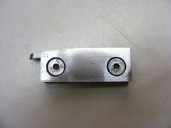
The cutter blank is held in this simple jig for the milling operation.The left hand side holds the cutter with a slight downwards inclination of 5 degrees and the right hand side may be used to hold the cutter in the horizontal position. There is a saw cut through the jig extending from the top almost to the bottom and the two countersunk screw are used to squeeze the slit closed and clamp the blank. The whole assembly is the clamped in a vice on the milling machine.
To set the cutter at the correct depth collars have been made as shown here. These collars were made using the cone drill and they simply slip onto the cone drill. The collar is slipped under the blank and the quill slowly raised. When the collar touches the blank it falls off the cone drill.
The only real problem that I have had is in achieving the correct tip width of the cutters. This seems to be due to the inherent lack of rigidity of my small milling machine. Any flexibility in the column results in a small tilt from the cutting force and this tilt means that the cone drill does not quite end up as close to the centre of the blank as it should. The error is doubled by the fact that the cone drill approaches from two different directions resulting in the tilt error being additive. The errors results in the tip width being wider than expected simply from the dial readings on the mill. The solution to this problem is to make the cutter and measure the tip width and then use the mill to adjust the tip width to the correct value by keeping the infeed the same. However, it is quite difficult to measure the tip width with any accuracy while the cutter is mounted on the mill ( it is only marginally easier once it is off the mill!!).
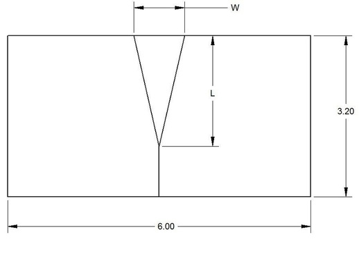
The diagram above shows an end view of the cutter. The tip of the cutter is the triangular section in the middle. The tip width is W and the length of the triangular section is L. It is much easier to estimate the length L than to measure the tip width. The table below is based on the table shown on the page "Designing gear cutters" but now includes the theoretical tip width and the tip length.
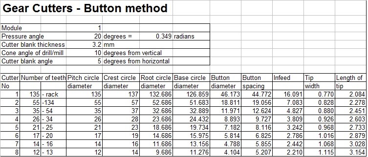
Copies of this spreadsheet are available on request. There is a contact form on the home page.
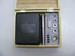
The complete kit for making gear cutter is shown here. The black box contains the cone drills, next to it is the cutter holder, in the grey foam can be seen the blank holder, the collars and the completed gear cutters
