Z - axis bearing
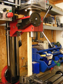
Since I first had the mill moving the headstock up and down the column has always been hard work. Turning the handle was always stiff, particularly when the headstock was near the top of the column. In fact I had never been able to wind the headstock right to the top of the column, it just became too stiff. I decided to investigate this problem and seek a solution.
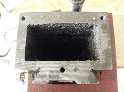
In order to investigate the problem is it necessary to dismantle the thrust block that is screwed to the back of the column. To do this the headstock must be supported. I cut a piece of wood, as shown here and gripped it in the mill vice. The headstock was lowered onto the piece of wood and the handle and thrust block was removed. The reason for the stiffness at the top of the column was immediately obvious. The bearing hole in the thrust block was not aligned with the feedscrew. I contemplated removing some metal from the back of the thrust block but in the end decided to replace the thrust block completely with a ball bearing.
The plastic cover stuck to the top of the column was removed. There was sufficient metal to permit a new cover to be made from steel that could be screwed onto the top of the column.
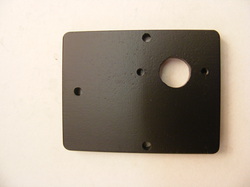
The new top plate was made from 8mm thick steel. Three holes were drilled for the screw positions to hold it to the top of the column. The hole positions were then transfered to the top of the column using a transfer punch. The top of the column was then drilled and tapped M4 at these positions, as shown in the previous photo. The large 16 mm hole in the top plate was drilled for the leadscrew.
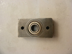
A bearing block was made from a piece of 10 x 25 mm steel flat. The bearing used was a 608ZZ with an inner diameter of 8 mm, an outside diameter of 22 mm and a thickness of 7 mm. The bearing block was was drilled out to 13 mm and then a recess for the bearing was bored out to slightly less than 7 mm. This leaves the rim of the bearing just above the surface of the block. Two 4.5mm holes were drilled, as shown, for bolting the bearing block to the top plate. The bearing block was counterbored to accept the heads of M4 socket head screws on the other side to that shown.
The components could now be assembled on the mill. First the top plate was screwed to the column and then the bearing block placed in position on the leadscrew. The holes in the bearing block were spotted through onto the top plate. The top plate was removed from the column and the marked position drilled and tapped M4.
The bearing block was loosely screwed to the top plate and the whole reassembled onto the top of the column and all the screws tightened.
The bearing block was loosely screwed to the top plate and the whole reassembled onto the top of the column and all the screws tightened.
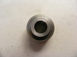
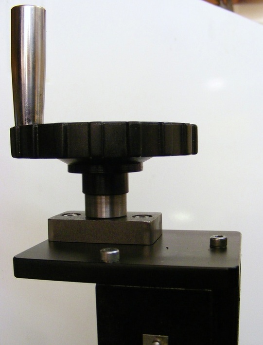
A small stepped spacer was made as shown here. The step is 3.5 mm long and 12 mm diameter and the outside diameter of the main piece was 18 mm. The hole is 8mm diameter to slide over the leadscrew shaft.
The final assembly is shown in the header photo. The new bearing block makes winding the column up and down much easier. In addition the headstock can be moved right up to the top of the column. This gains 20mm of working height because travel is no longer limited by the thrust block on the back of the column.
