Ball turning attachment
Sieg produce a ball turner for the minilathe. Their version swings around the workpiece in the vertical plane. The problem with ball turners that operate in the vertical plane is that unless the workpiece is a long way out from the chuck there is an inevitable conflict with the chuck itself. Ball turners operating in the horizontal plane are less restrictive from this point of view. There have been many ball turners designed for the minilathe that operate in the horizontal plane and most of these are based on the original design of Steve Bedair. All the versions I have seen use a TCMT carbide insert as the cutting tool. The insert is usually mounted with the tip of the insert on the mid line of the attachment with one of the corners pointing forward. The problem with this arrangement of the tip is that the width of the insert prevents the tip from actually approaching the supporting shaft on which the ball is mounted. This results in a shoulder where the ball joins the mounting shaft that must be machined away afterwards.
Conceptually, the design presented here follows the basic philosophy of the Steve Bedair design and also uses a TCMT insert. However, the construction is rather different and the placement of the insert is changed to allow the cutting tip to approach right up to the supporting shaft permitting a true unshouldered ball to be turned.
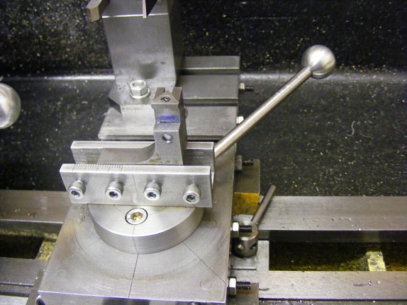
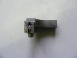
The header photo shows the complete unit. It consists of several components. The base plate is a disc of steel that is bolted to the cross slide turntable. A handle is attached to the disc so that it can be rotated easily on the turntable. On the disc is mounted a steel channel section. This is bolted to the base plate from underneath. In the channel sits the pillar component that supports the insert carrier. The pillar can be slid in the channel to adjust the size of ball required and locked into position by clamping screws at any point. The channel carries a graduated scale in millimetres to allow easy adjustment of the ball size. The insert carrier is another piece of steel that is bolted to the pillar.
Conceptually, the design presented here follows the basic philosophy of the Steve Bedair design and also uses a TCMT insert. However, the construction is rather different and the placement of the insert is changed to allow the cutting tip to approach right up to the supporting shaft permitting a true unshouldered ball to be turned.
The header photo shows the complete unit. It consists of several components. The base plate is a disc of steel that is bolted to the cross slide turntable. A handle is attached to the disc so that it can be rotated easily on the turntable. On the disc is mounted a steel channel section. This is bolted to the base plate from underneath. In the channel sits the pillar component that supports the insert carrier. The pillar can be slid in the channel to adjust the size of ball required and locked into position by clamping screws at any point. The channel carries a graduated scale in millimetres to allow easy adjustment of the ball size. The insert carrier is another piece of steel that is bolted to the pillar.
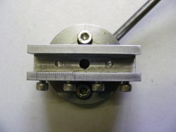
This shows the base plate and channel section. The base is a 50 mm diameter disc of steel and the channel was machined from a piece of 19 mm square bar. The slot width is 10 mm. The screws on the base are for attaching the disc to the cross slide turntable. Within the channel can be seen the ends of the screws that bolt the channel to the base plate from underneath. The four clamp screws for the pillar are M4. The handle seen protruding form the base is 6 mm round bar screwed into the disc. It is angled about 10 degrees up from the plane of the base to provide a little more working clearance. The handle terminates with an aluminium ball made with the ball turner. Note the scale scribed on the channel section. The end of the pillar section is the indicator for the scale.
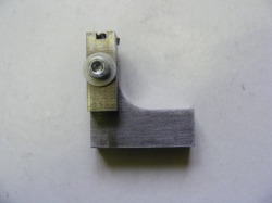
Shown here is the pillar with the insert carrier. The pillar is fashioned from a piece of 10 mm thick bar and slides in the channel section. The insert carrier is made from a piece of 10 mm square bar and is bolted to the pillar by an M4 screw.
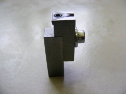
This is another view of the pillar and insert carrier. This shows the orientation of the insert and how it is set to lie on the mid line of the pillar.
This photo was taken looking down on the insert. The insert recess was machined with a 3 mm slot drill. The insert was glued in place with cyanoacrylate adhesive and then the hole was drilled for the securing screw. A little heat softens the adhesive and the insert can be removed to allow tapping of the hole.
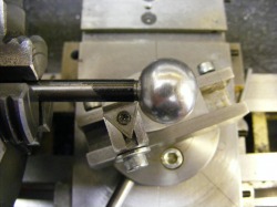
This shows the tool in action and shows that with the new placement of the insert it can cut right up to the supporting axle of the ball.
The ball turner has been used to cut balls in plastic, aluminium and mild steel without any problem. It has a capacity to cut balls up to 40 mm diameter and it is easy to mount and dismount on the lathe.
