Bandsaw cut off table Mk2
The first version of the bandsaw cut off table was designed primarily to support the piece being cut and to catch the piece once it detached. This new, improved version keeps these functions and, in addition, it provides a calibrated depth stop that allows a fixed length of material to be cut off.
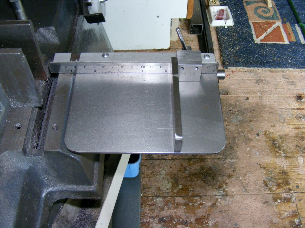
The header photo shows the rule and a sliding depth stop that can be locked any where along the scale using the small lever sticking up on the far side of the rule.
The band saw is supplied with a rather crude depth stop. This is a casting that slides on a bar that protrudes from the bandsaw base casting. This bar is used to support the table.
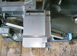
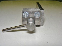
The table is 150 mm long and 125 mm wide. It is supported by two block made from 25 x 10 mm steel that slide on the depth stop bar as shown here. The blocks are attached to the table using two M4 screws in each block. Another M4 screw, seen protruding from the left hand block in the photo, clamps the table to the bar
The holes for the stop bar were drilled 17.5 mm from the end since this sets the table at the same height as the base of the bandsaw vice. However, after assembly the table was not parallel with the vice base. This was because the stop bar hole in the bandsaw base casting caused the bar to slope upwards. It was necessary to mill 2 mm from the block on the right hand side in order to get the table parallel with the vice.
The holes for the stop bar were drilled 17.5 mm from the end since this sets the table at the same height as the base of the bandsaw vice. However, after assembly the table was not parallel with the vice base. This was because the stop bar hole in the bandsaw base casting caused the bar to slope upwards. It was necessary to mill 2 mm from the block on the right hand side in order to get the table parallel with the vice.
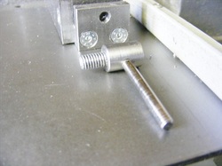
A piece of 15 x 30 x 2 mm steel angle is attached on the right hand side of the table using the same screws that secure the blocks to the table. Initially the angle is cut a little longer than required and it is cut to length once the table is mounted on the bandsaw. This ensures that the end of the angle lines up exactly with the bandsaw blade.
A cut out in the angle is milled out to enable the grub screw that secures the stop bar into the bandsaw base casting to be tightened.
A cut out in the angle is milled out to enable the grub screw that secures the stop bar into the bandsaw base casting to be tightened.
The scale shown in the header photo was made from an 200 mm engrave steel rule. This was 20 mm wide the width was reduced to 15 mm using a slitting saw. The angle and the back of the rule were abraded with fine wet and dry paper to roughen both surfaces and then coated with epoxy adhesive. They were then pressed together, excess adhesive removed an left clamped in a bench vice to cure.
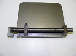
The sliding stop bar is made from 6 x 25 x 100 mm steel.
The clamp is fabricated from three pieces. The right hand side of the clamp is a piece of 12 x 25 mm bar 25 mm long. The gap is 3 mm wide and formed from a piece of steel 3 x 9 x 25 mm. The short arm of the clamp is made from another piece of steel 6 x 20 x 25 mm.
The clamp is fabricated from three pieces. The right hand side of the clamp is a piece of 12 x 25 mm bar 25 mm long. The gap is 3 mm wide and formed from a piece of steel 3 x 9 x 25 mm. The short arm of the clamp is made from another piece of steel 6 x 20 x 25 mm.
The pieces forming the clamp are held together with two M4 countersunk screws
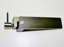
The stop bar is also attached to the clamp with a single M4 countersunk screw.
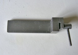
The clamp screw was turned from 10 mm steel round 24 mm long.This was reduced to 6 mm for a distance of 9 mm and then threaded M6.
The piece was cross drilled 3.3 mm and tapped M4. The lever was formed fro a 40 mm length of 4 mm round that was threaded M4 for 5 mm.
The piece was cross drilled 3.3 mm and tapped M4. The lever was formed fro a 40 mm length of 4 mm round that was threaded M4 for 5 mm.
