Bandsaw hydraulic cylinder
The standard 6 x 4 bandsaw has a spring tensioner that controls the force exerted on the workpiece being cut. This control works fine for cutting solid workpieces. The force can be varied to provide a coarse finish on the cut with a heavy load or a very fine finish if the load is light. However, if the object being cut is thin, or a thin walled tube, then, no matter what the load the teeth of the blade are likely to snatch the material and these can break the teeth off the saw blade. Conventional wisdom says that to avoid this situation then at least three teeth must be in contact with the object being cut.
More up market bandsaws are equipped with a hydraulic damper that controls the rate of descent of the saw blade. If the rate of descent is set very slow then even on thin walled tube the saw blade just nibbles away at the material being cut rather than taking big bites and tooth breakage is eliminated.
Many users in the US have fitted hydraulic cylinders to their 6 x 4 bandsaws. In the US hydraulic cylinders seem to be available cheaply as surplus items whereas on this side of the pond cheap hydraulic cylinders seem to be as rare as honest politicians. I did investigate door closure dampers as a possible route but the specifications for these units, which relate to doors not bandsaws, makes a choice difficult.
In the end I decided to make my own hydraulic damper as shown in the header photo. It consists of a copper cylinder which is easily fabricated from standard plumbing fittings. Inside the cylinder is a steel piston sealed with a rubber o ring. The piston incorporates a non return flap valve that opens when the saw arm is lifted and provides an easy path for the hydraulic fluid. This means there is little resistance from the cylinder when lifting the arm. The flap valve closes automatically when the saw arm is lowered and the only path for the hydraulic fluid is via a needle valve. Depending on the opening of the needle valve the rate of descent of the saw arm can be controlled from very near stationary to several metres per second.
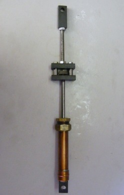
This shows the complete unit. It consists of a copper cylinder, closed at one end. The closed end is bolted to a steel pivot block made from 10 x 20 hot rolled bar with a 10 mm hole for the pivot. The upper end of the cylinder is closed by a compression fitting drilled out with a 8 mm hole for the piston rod. The end of the piston rod screws into block of 10 x 20 mm hot rolled steel. Above this block is the adjuster knob that operates the needle valve controlling the flow of hydraulic fluid. Separated by spacers is another identical block of hot rolled steel into which is screwed the push rod that connects to the upper pivot block also made from 10 x 20 mm hot rolled steel bar.
The cylinder itself is made from a piece of 22 mm copper tube 130 mm long. One end is sealed with a copper end cap ( stop end in plumbing parlance) which is soft soldered in place. The end cap is then drilled with a 6 mm hole and bolted to the bottom pivot block using a 6 mm hex head screw and washer. The copper being soft makes a good seal.
The cylinder itself is made from a piece of 22 mm copper tube 130 mm long. One end is sealed with a copper end cap ( stop end in plumbing parlance) which is soft soldered in place. The end cap is then drilled with a 6 mm hole and bolted to the bottom pivot block using a 6 mm hex head screw and washer. The copper being soft makes a good seal.
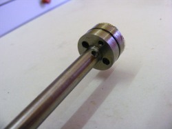
The piston is 20 mm diameter and the seal with the cylinder is formed by an o ring that sits in a groove machined in the periphery. The two holes in the piston go right through the piston to the other side. The piston rod is 8 mm diameter and 120 mm long. It is drilled out with a 4 mm drill for the entire length. The piston rod end is threaded M8 and screws into a threaded hole in the piston. The threaded hole in the piston does not go all the way through the piston and the last 2 mm are drilled with a 1 mm drill. This small hole makes the seating for the needle valve. Note the 3 mm hole drilled in the piston rod just above the piston. This is to allow the hydraulic fluid passing through the needle valve to flow to the other side of the piston.
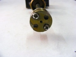
The other side of the piston shows the small 1 mm diameter hole in the centre. The two M3 screws secure a sheet of thin plastic over the end. This forms the flap valve. If the piston is being raised the plastic flaps open by the flow of oil passing from above the piston to below the piston. If the cylinder is being lowered then the flaps are pushed firmly back against the two holes and the only flow is then through the central hole controlled by the needle valve.
This is the plastic disc that forms the flap valve. It was cut from a piece of blister packaging that so many items are packed in these days. It is approximately 0.2 mm thick. This piece of plastic has been in use for 4 years and does not seem to be showing any signs of wear or stress.
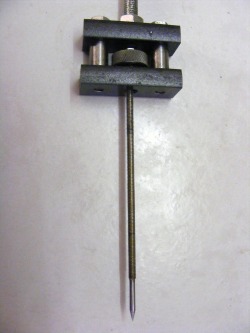
The needle is machined from a piece of 4 mm steel studding. The end is turned down to 3 mm and the conical tip is 6 mm long. At the top the lower carrier block is part threaded with an M8 thread at the bottom to accept the piston rod and part threaded at the top with an M4 thread which the needle valve screws into. The knurled adjuster knob screws onto the portion of the M4 threaded rod that emerges through the lower carrier block and it is locked in place by a lock M4 lock nut. Thus turning the adjuster knob raises and lowers the needle valve,
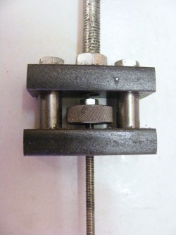
This is a close up of the carriers and the adjuster knob. The lock nut can be seen above the adjuster knob. The spacers either side of the adjuster are 10mm diameter and they were bored out 6mm. The two carriers are bolted together through the spacers by M6 screws. The upper carrier block is threaded centrally M8 for the push rod going to the upper pivot block.
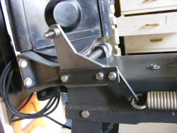
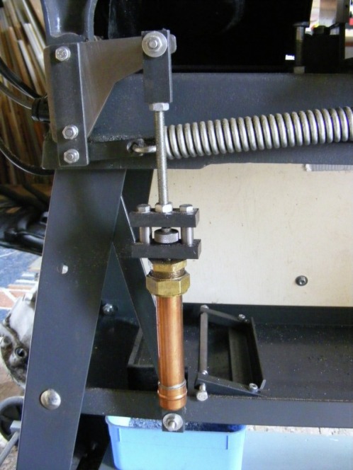
The upper attachment bracket is attached to the bandsaw at two points. The pivot shaft for the bandsaw arm hinge was drilled and tapped M6. This provides one fixing point. The second fixing point is the hole into which the tensioning sping normally fits.The bracket is bolted in place with M6 screws. The tension spring is attached to the bracket by a freely swinging link as shown above. At the top of the bracket is the pivot point for the hydraulic cylinder assembly.
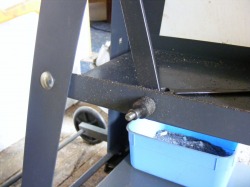
The lower attachment point for the hydraulic cylinder assembly is on the shelf and is immediately below the upper attachment point when the bandsaw arm is in the lowered position. The shelf edge was reinforced along the whole length with a piece of 3 x 25 x25 mm steel angle and a brace added that attaches to the bandsaw casting to make a rigid attachment point.
This shows the actual attachment point for the upper pivot block of the hydraulic cylinder assembly. There is a shouldered axle made from 19 mm round bar turned down to 10 mm which the upper pivot block slips over. The axle is secured in place with an M6 screw and washer. The bottom attachment point is identical apart from the length of the shoulder which was adjusted so that the two pivots were one the same vertical plane.
The cylinder is filled with oil before use. I used SAE 90 EP oil because it was available but I think almost any oil with a reasonable viscosity would do.
The unit has been in use for 4 years it has had no maintenence at all and has worked reliably throughout that time. Total expenditure on material must have come to about £2-3 (circa 3-4 USD) and for that price you cannot buy a surplus hydraulic cylinder even in the US.
Detailed drawings of the hydraulic cylinder are available in the files section of http://groups.yahoo.com/group/4x6bandsaw/
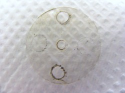
Replacement disc for flap valve.
After about 8 years use, closing the needle valve no longer stopped the descent of the bandsaw arm. On dismantling the hydraulic cylinder and examining the flap valve membrane some hairline cracks were evident in the plastic where it covers the holes in the piston. A new plastic disc was cut for the flap valve and after reassembly the hydraulic cylinder functioned normally.
Fabricating the piston rod.
Making the original piston rod was a real pain. The piston rod is 120 mm long and even drilling from both ends it took a great deal of time because after each millimetre cut then the drill must be withdrawn to clean out the flutes. This is a great deal of handle winding and the whole drilling operation probably took a couple of hours. I came across some 10 mm steel tube with a wall thickness of 1 mm and I wondered whether it would be possible to fabricate the piston rod by making two inserts and fixing them at either end of a piece of this tube.
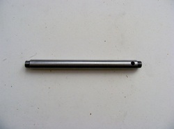
The tube ( actually an offcut of curtain rod from IKEA) was first cleaned up and the paint removed by heating and scraping. Once cleaned, a piece 115 mm long was mounted in the lathe and the outside polished with fine emery cloth. The tube was resistance welded tube and there was an internal seam which projected slightly into the bore. Both ends of the tube were faced and then drilled out 8 mm diameter for a length of 20 mm to remove the projecting seam.
Two pieces of 8 mm steel rod were cut 25 mm long. These were a loose fit in the steel tube so they were chucked in the lathe and knurled for a distance 20 mm until they were a good snug fit in the tube. They were then turned around in the lathe chuck and threaded M8 for a distance of 7 mm.
The two inserts and the tube were degreased in white spirit and dried with clean tissue. A small amount of epoxy resin was mixed up and applied inside the ends of the tube and to the knurled ends of the inserts. The inserts were then tapped into the tube so that 5 mm of thread was protruding. Excess epoxy was wiped off and the piston rod was left to cure overnight.
The piston rod was then chucked in the lathe and the inserts were drilled through with a 4 mm drill. The thread was cleaned up with a die to remove any excess adhesive in the thread.
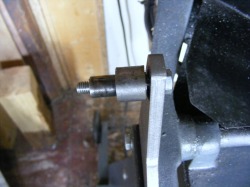
The piston rod was then cross drilled with a 4 mm drill as shown here.
Using the tube and the inserts to make the piston rod eliminates the very tedious deep hole drilling of the solid piston rod. The hole in the compression fitting at the top of the bandsaw hydraulic cylinder needed to be opened out to 10 mm from the original 8 mm diameter hole for the new piston rod but otherwise everything else is the same.
