Bandsaw stop
Sometimes when using the bandsaw it is necessary to measure the amount of material protruding beyond the blade. If the protrusion is large it is possible to rest the blade on the material to be cut, measure from the end of the material to the blade, then lift the bandsaw arm to alter the position of the material, drop the arm, re-measure etc until the protruding length is correct. It is even more complicated when the protrusion is small because when the blade is lowered it tips the material into the blade gap of the bandsaw. The blade must somehow be supported above the material, the position measured and adjusted, and the vice tightened before the blade can be lower to contact the material. More than two hands are required for this operation and I tend to support the bandsaw arm using my knee whilst fiddling with ruler, altering the position and doing up the vice.
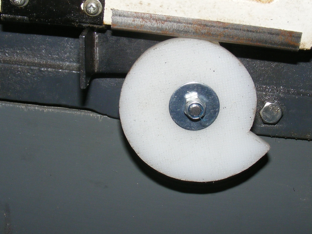
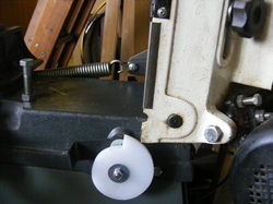
I thought there must be a better way to support the arm so that the bandsaw blade was just above the material being cut leaving both hands free for measuring and positioning. The solution that I came up with was a cam close to the rear of the bandsaw arm pivot point as shown in the header photo. By rotating the cam the bandsaw arm can be stopped at any convenient point above the material.
I thought there must be a better way to support the arm so that the bandsaw blade was just above the material being cut leaving both hands free for measuring and positioning. The solution that I came up with was a cam close to the rear of the bandsaw arm pivot point as shown in the header photo. By rotating the cam the bandsaw arm can be stopped at any convenient point above the material.
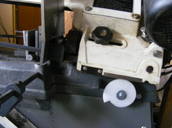
This photo shows the cam rotated so that it supports the arm just above a piece of 16 mm round bar in the vice.
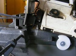
Here the cam has been rotated some more and the bandsaw arm is supported much higher.
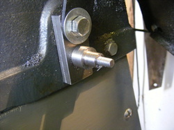
The cam is supported on shaft secured to a block of steel. This is fixed to the bandsaw casting using the M8 screw already present that secures the metal bracket that locks the saw arm in the vertical position.
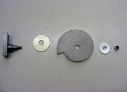
The components are the shaft and steel block shown above, a 10mm penny washer, the cam, a small 6 mm penny washer and an M6 lock nut.
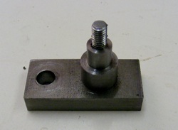
The pivot block was made from a piece of steel approx 50 x 22 x 10 mm. This was drilled out at the left hand side M8.5. This hole is for the M8 screw that secures it to the bandsaw casting. The right hand side was drilled out 5 mm and then tapped M6. A piece of M6 threaded rod is screwed into the block.
The pivot was turned from a piece of 16mm round steel bar. This was centre drilled and then drilled out 5 mm for a depth of 22 mm. This was tapped on the lathe until the tap was well started in the material. The end of the bar was then turned down to 10 mm diameter for a length of 9.5 mm. Finally the bar was parted off at 10 mm from the shoulder. This piece was then gripped in the vice and tapped all the way through.
The pivot was screwed onto the threaded rod and tightened but gripping it in the vise and turning the block.
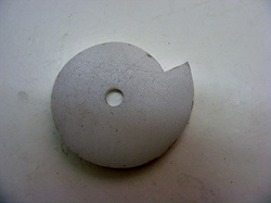
The cam was made from a piece of polyethylene (PE) sheet that was 9 mm thick (actually an old kitchen chopping board). The shape of the cam was drawn using a CAD program. It is designed to increase in radius from 30 mm to 45 mm linearly over a 270 degree angular range with the last quadrant having a constant radius of 30 mm.
The CAD drawing was printed out at a 1:1 scale, sprayed with contact adhesive and the stuck to the 9 mm PE sheet. The shape was cut out using a small woodworking bandsaw with a narrow (6mm) blade. The shape was cleaned up and blended using a belt sander. The centre point was centre punched and then drilled out 10 mm to fit the pivot shaft.
The CAD drawing was printed out at a 1:1 scale, sprayed with contact adhesive and the stuck to the 9 mm PE sheet. The shape was cut out using a small woodworking bandsaw with a narrow (6mm) blade. The shape was cleaned up and blended using a belt sander. The centre point was centre punched and then drilled out 10 mm to fit the pivot shaft.
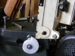
The edge of the casting on the bandsaw arm is very rough with nicks to allow the lock bracket to be used to support the saw arm in three positions. The nick at the bottom supports the arm in the vertical position.
To provide a smooth surface for the cam to operate against a piece of 10 x 10 x 1 mm steel channel was cut 90 mm long. This is resting on the top of the bandsaw in this photo.
To provide a smooth surface for the cam to operate against a piece of 10 x 10 x 1 mm steel channel was cut 90 mm long. This is resting on the top of the bandsaw in this photo.
This piece of channel clips over the edge of the bandsaw arm, as shown here. No screws or other fixings were necessary to retain the channel. Note that the bottom nick is retained so that the bandsaw arm can still be locked into the vertical position using the locking bracket. This is an important safety feature when using the bandsaw in the vertical position.
This is a very simple modification to make to the bandsaw but it makes it much easier to set up.
