Carriage DRO
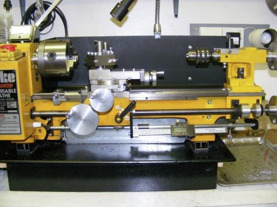
A digital read out (DRO) is very useful for accurate positioning of the carriage along the lathe bed. My set up was constructed from a cheap digital caliper. I wanted to position the DRO well away from the tool post to avoid cutting fluids and swarf splashing the unit. The photo above illustrates the set up. A 10 mm horizontal bar has been added to the lathe just below the lead screw. This is attached to the lathe bed casting by two bracket at either end. One end of the modified digital caliper is attached to a bracket mounted on the carriage. The bracket is attached to the carriage using the tapped hole normally used for the threading indicator. The sliding display of the caliper is attached to a slider that runs on the 10 mm bar and this can be locked onto the bar at any point using a knurled brass screw situated immediately above the display. With the slider locked onto the bar then any movement of the carriage is registered on the DRO display. Also shown on the bar are two sliding collars with knurled screws attached. These are stops and they can be used to set limits to the carriage movement to the left or right or both.
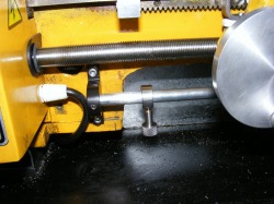
This shows the left hand end of the bar. It is mounted in a bracket made from 50 mm x 10 mm steel bar. The bracket is secured to the lathe bed by two M4 socket head screws. Note the grub screw in the centre of the bracket. This secures the bar to the bracket.
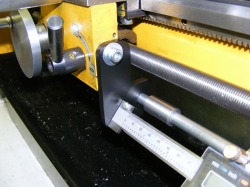
This shows the bracket at the right hand side of the lathe. This is attached to the underside of my lathe bed extension. However a suitable bracket could also be attached to the end of the lathe bed of a standard lathe without the bed extension.
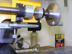
This shows the bracket attached to the carriage. It is made from a piece of 1/4" plate. The 10 mm round bar passes through the plate. The hole for this is bored out 12 mm allowing a 1 mm clearance. The end of the DRO is attached to another small bracket mounted on the plate. Note the loose collar on the bar. This is there so that if the right hand end stop is in use then the force when the carriage hits the stop is transmitted through the collar rather than the more delicate DRO. The DRO is angled at 30 degrees from the vertical for easy reading.
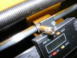
This shows the display mounting on the bar. The mounting is a collar which has a flat face milled onto it. The display is attached to a piece of steel strip and this is then attached to the flat face on the collar with M3 screws. The clamp bolt is made from brass and is knurled at the end for easy locking. Note also that a simple folded plastic cover has been added to protect the display from oil and swarf. The cover was made from plastic salvaged from some packaging which was cut out and then folded to shape.
This DRO mounting works very well. The display is well out of harms way. Although the caliper only has a 150 mm range this is sufficient for most operations. If greater range is needed it is easy to do this in two or more stages.
