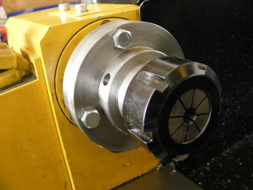
ER32 collet chuck
Collet chucks are very convenient to use for operations requiring presevation of concentricity even after removal and replacement in the chuck.
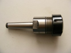
I purchased this collet chuck from a company called CTC tools (www.ctctools.biz), based in Hong Kong, together with a range of 10 ER32 collets. The collet has an MT2 Morse taper fitting. At the time the main reason for buying the chuck was to hold cutters in my Sieg milling machine. The collet is well made and the runout for a typical cutter is typically around 0.01 mm. I could also use this chuck in the minilathe using an MT2 to MT3 adaptor. The disadvantage of this set up on the lathe is that the collet protrudes a long way from the spindle flange and the workpiece length is limited to around 25 mm.
The obvious solution to these problems was to make a flange mounted chuck. This brings the chuck much closer to the spindle flange and also allows long workpieces since they can pass into the spindle bore. In making such a collet chuck the most important requirement is that the chuck register on the flange should precisely match the register in the back of the chuck. If this is wrong then then it will be impossible to relocate the chuck on the spindle in a reproducible way. The first job that had to be done was to make a plug gauge with exactly the same dimensions as the flange register. The plug gauge was turned from a piece of 60 mm steel until it was an exact fit into my other chucks. I have four chucks in total: a 3 jaw 80 mm chuck, a 4 jaw 80 mm, a 3 jaw 100 mm and a 4 jaw 100 mm. The 3 jaw 100 mm was mounted on the lathe holding the steel for the plug gauge so the gauge was turned to a diameter that would just enter the other three.
I could have turned the chuck from a piece of 80 mm round bar. However, I have an aversion to spending good money on a piece of metal only to see most of it converted into worthless swarf. Instead I opted to fabricate the chuck from a piece of 10 mm hot rolled plate for the flange and a piece of 50 mm diameter free cutting mild steel bar for the chuck body.
First the 10 mm plate was marked out. The outside diameter was marked (80 mm) using dividers, and then with the pitch circle diameter (66 mm) of the mounting screws. The PCD was then divided into four at 90 degree intervals. 6 mm holes were drilled and tapped at the four intersections for the mounting studs. The plate was then roughly trimmed to the outside diameter on the bandsaw by first cutting a square and then cutting the corners off to create an octagon. Four studs were cut from M6 studding and screwed in place. Four M6 nuts, selected to be of equal thickness, were then run onto the studs and locked in place. These nuts act as stand offs when the plate is bolted to the spindle. Once firmly bolted to the spindle flange the OD was turned to 80 mm and then faced. A hole was drilled in the centre and this was opened out to 36 mm. The plate was then dismounted from the spindle and the three jaw chuck mounted.
A 40 mm length of the 50 mm round bar was then chucked and faced. The end was then turned down to 36 mm for a depth of 10 mm so that it was a loose fit in the plate.
The hole in the plate and the shoulder of the round bar were then coated in Easyflo flux. The two parts were assembled together with some small pieces of silver solder in the joint. This was then heated to a dull red heat until the solder flowed. When it had cooled to below red heat it was quenched in water to remove the excess flux.
This assembly was then chucked in the lathe by the 50 mm round section and the flange faced. It was then drilled and bored out to 22 mm. The register recess was then very carefully cut until the plug gauge just fitted.
The assembly was removed from the chuck and the chuck removed from the spindle. The fit of the register on the flange on the spindle flange was then checked. No perceptible movement could be detected. The studs were screwed into the tapped holes and the assembly bolted to the spindle flange.
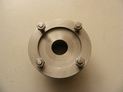
This photo shows the finished register in the flange. The junction of the hot rolled steel and the free cutting steel can be clearly seen.
With the assembly now bolted to the spindle flange the outside diameter of the flange was skimmed as well as the flange face and the outside of the 50 mm round bar. Next the end of the bar was faced and the bar turned down to 40 mm for a length of 18 mm.
The next operation was to thread the bar for the collet cap nut. This has a 1.5 mm pitch. First a run out groove for the thread was cut. The groove was 1.5 mm deep and 5 mm wide. The bar was then screw cut from the end to the run out groove. The thread was checked often in the final stages of screw cutting with the collet cap nut. The nut should run freely but not be loose.
At this stage mark the collet chuck flange and the spindle flange with small centre punch marks so that it can always be replaced on the spindle in the same orientation. Then remove the collet chuck from the spindle. The next operation is cutting the collet taper.
To set up the taper the purchased MT2 collet chuck was mounted in the spindle using an MT2-MT3 adaptor. With a dti set up at centre height on the toolpost the top slide angle was adjusted so that there was no deflection of the dti when it was run along the inside of the collet chuck taper . The topslide was then firmly locked in place. The chuck was then removed from the spindle and the new flange mounted chuck remounted on the spindle flange.
The internal taper was then cut taking small cuts each time. Periodically during the procedure the taper was tested with a collet to check the depth of the taper. Approximately 13 mm of the collet should protrude from the taper.
The final operation is drill the four holes around the collet to accept a tommy bar. These can be clearly seen in the header photo.
I replaced the studs by hex head screws rather than have the stud holes visible.
If I were making the unit again I would just use three mounting studs.
