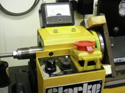
Headstock upgrade
This project was started in order to improve the headstock. Many other owners of the minilathe have reported much better headstock rigidity by changing the bearings from ball bearings to taper roller bearings and this significantly improves the performance of the lathe in critical situations such as parting operations. A pair of 30206 taper roller bearings was ordered on ebay.
Recently Real Bull, a Chinese company that manufactures a minilathe clone, has introduced a new minilathe with a 100 mm spindle flange. This new development enables a 100 mm chuck to be directly attached to the spindle thereby saving the space occupied by and the inaccuracies inherent in an adaptor plate.
Jose on his toolsandmods website (www.toolsandmods.com) has already described the fitting of the new 100 mm spindle to his Real Bull lathe and after some email discussion with him it seemed that the dimensions of the spindle were identical to the Sieg spindle. On the basis of this I went ahead and ordered the new spindle from Amadeal (www.amadeal.co.uk). This cost £36.
The new spindle had some slight rust stains on the external surfaces but this was not really significant and these were easily polished off using steel wool. The taper appeared to be in good condition although the bore of the spindle was heavily rusted internally. The bearings would not slide on the spindle because it was slightly oversize and the first job was to polish the spindle. To do this the an MT2 taper centre was entered into the spindle taper and it was then mounted on the lathe by gripping the screwed end of the spindle in the lathe chuck (with aluminium packing to avoid damage to the threads) and locating the taper centre in a female centre in the tailstock. Using 600 grade emerycloth and oil the shaft was then polished until the bearings were a tight sliding fit on the shaft.
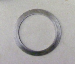
The taper roller bearings have slightly different dimensions to the ball bearings they replace (see www.toolsandmods.com/mini-lathe-headstock.html for details). In order to compensate for the differences two washers were made from 38 mm round stock. This was bored out to 30 mm (the spindle shaft diameter) and then parted off to make two 1.25 mm thick washers. Using this method to compensate for the differences means that all machining can be carried out before dismantling the headstock.
The spindle retaining nuts at the back of the headstock were next removed along with forward/reverse selector and cover, the drive gear to the leadscrew, the key and the long black plastic spacer. The bearing covers were removed from the bearings at the front and the back of the headstock.
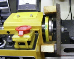
This shows the simple arrangement used to pull the bearings from the head stock. After unscrewing the plastic bearing cover a piece on M10 studding was passed through the spindle and then through a piece of 2"x 1/2" steel plate as shown here. The ends of the steel plate were braced against the headstock casing using two pieces of 1.1/2" x 3/4" softwood.
At the rear of the spindle the M10 stud passed through a thick washer. By tightening the nut at this end the bearing was drawn from the headstock.
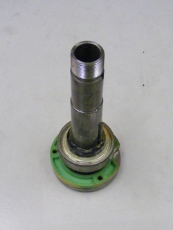
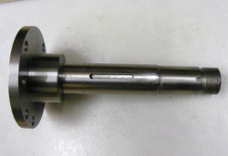
This shows the old spindle with the bearing attached. Above the bearing is a black plastic spacer, this just slides off, and below the bearing is the plastic bearing cover. The key was removed from the shaft. The bearing was a tight fit on the shaft. In order to remove it a piece of 2 metre long 15 mm copper tube was inserted through the spindle. The tube was positioned vertically over a piece of 10 mm thick aluminium plate resting on a solid surface. The spindle, threaded end down, was slid to the top of the tube and allowed to fall, guided by the tube, onto the aluminium plate. The impact caused the bearing to move a little. Repeating this process many times, (circa 25 times) resulted in the bearing dropping off the spindle shaft. The threaded end of the shaft was not damaged. The bearing cover was then recovered for later re-assembly on the lathe. The old spindle will be recycled at some stage to make a dividing head.
The next step was to remove the other bearing from the back of the headstock. This was done using a length of brass rod as a drift and working round the bearing using small taps of the hammer. The only complication here was that care must be taken to avoid damage to the spindle gear and plastic spacer which is floating around inside the head stock. Once the bearing was out of the way the plastic spacer can be removed from the headstock. With both bearings out it was time to start the re-assembly.
The outer bearings were tapped into the bearing recesses in the headstock using a brass drift until they were fully seated. The inner bearings were packed with grease. I used Castrol MS3 grease which contains molybdenum disulphide. The front end of the spindle was next prepared. First to go on is the bearing cover, then a 38 x 4 mm "O" ring. This acts as a seal to prevent ingress of swarf to the bearing. It simply sits on the shaft and fits into the groove already moulded into the bearing cover. The bearing was slid on followed by the 1.25 mm steel washer and the plastic spacer. The key was tapped into the recess on the new spindle. The spindle shaft was then pushed through the gear inside the headstock ensuring that the keyways line up. Now the back end of the spindle was assembled. First to go on was the plastic spacer then the 1.25 mm steel washer, followed by the bearing. The long plastic spacer goes on next. The keyway in the spindle for the leadscrew drive gear is shorter (6mm) than the keyway in the Sieg spindle (8mm) so a new shorter key was cut from 4 mm steel plate and filed to a good fit. Once the key was in place the leadscrew drive gear and one of the ring nuts was added to the shaft. The ring nut was tightened up hard to bed the bearings in position. The bearing covers were screwed into position and the forward /reverse gear and cover were replaced. Inspection of the assembly at this stage showed that the leadscrew drive gear was out of alignment with the forward/reverse gears by about 1.5 mm. The ring nut and gear were removed along with the key and the long plastic spacer was withdrawn. This was replaced with a piece of 1.1/4" plastic waste pipe of about the same length and then the gear and ring nut replaced. The three jaw chuck was put on the front of the spindle. With this temporary assembly in place the long plastic spacer was reduced in length in the lathe by 1.5 mm. The temporary assembly was then dismantled and the new spacer put it place and then the gear and ring nut. Inspection showed that the leadscrew drive gear now lined up well with the forward/reverse gears. The ring gear was tightened to bed the bearings into place and the lathe turned over slowly for a few revolutions. The ring nut was then backed off about 1/4 turn and the second ring nut, in my case the spindle extension nut, then tightened against the first ring nut to lock it in place.
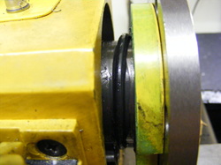
This shows the "O" ring and the bearing cover before the cover was screwed into place.
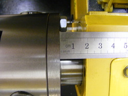
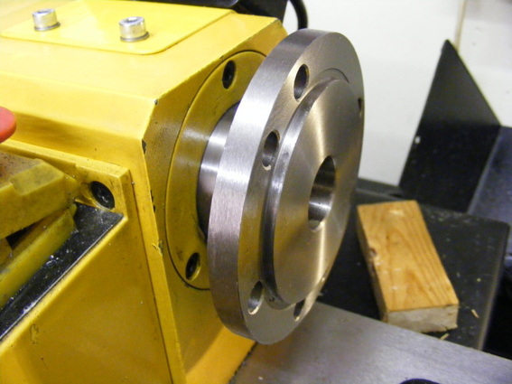
The gap between the spindle flange and the headstock has increased to 19 mm following the conversion. This, together with the bigger pitch circle diameter of the holes in the flange, makes taking the chuck on and off much easier than when using the old spindle with an adaptor plate.
This project was surprisingly straightforward and the only real surprise was when it came to fitting the key for the leadscrew drive gear. This has to be slightly shorter to fit the new spindle. The benefits of the conversion are: more distance between chuck and tailstock, greater rigidity, easier chuck removal and replacement and less inertia. Another point to note is that before the conversion my lathe suffered from vibration at around 750 rpm spindle speed. After the conversion this vibration has completely disappeared. The original vibration must have been due to the 100 mm chuck adaptor plate. This is thick with many holes and counterbores that are not symmetric so it was inherently unbalanced. The new flange also has many holes assymetrically disposed around the flange but there are no counterbores and the flange is only 9mm thick so the imbalance is much less.
