MIG welder modifications
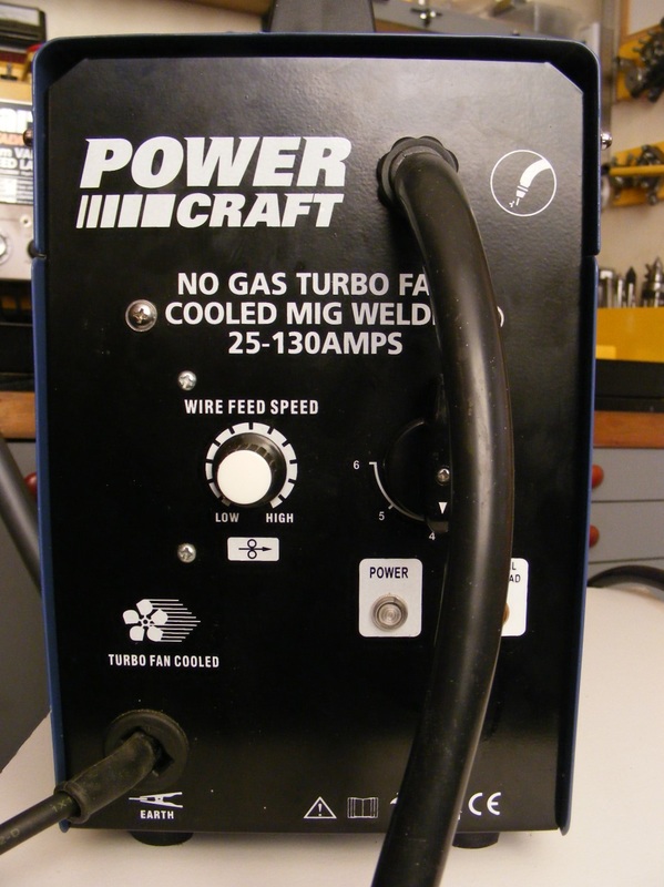
My MIG welder was purchased from ALDI. It is a gasless welder that uses flux cored welding wire. It is relatively easy to use and with some practice I was able to produce acceptable welds. The down side to a gasless welder is that there is more spatter than from a with gas welder and after each pass it is necessary to chip of the slag from the top of the weld bead. Having had the welder for some time I started to wonder whether it would be possible to convert it to use a shielding gas.
The differences between gasless and with gas MIG welders are few. A with gas welder has a gas supply which runs from a cylinder through the welding cable sleeve to the welding torch. At the torch there is a valve to turn the gas on whenever the trigger on the torch is actuated. The other main difference is that for gasless welding the work is positive and the torch is negative whereas for with gas welding the torch is positive and the work is negative.
With these difference in mind I started to investigate the feasibility of converting the welder to with gas operation. I dismantled the torch and discovered that the torch already had the gas valve but it was not connected to a gas supply. Opening up the side of the welder also showed it would be simple to bring the earth clamp and torch welding cables up to a small terminal block inside the wire feed compartment. The welding power supply could then be fed into the wire feed compartment on flying leads so that they could be connected to the terminal block with either polarity.
The gas supply.
The first requirement was to install a 4 mm nylon gas tube through the sleeve that connects the torch to the welder.
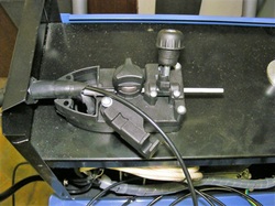
At the welder end the cover on the wire feed unit was removed and this allows access to the end of the sleeve connecting the torch to the welder. There was plenty of room in the sleeve for the 4 mm nylon tube and with the sleeve laid out straight it was easy to feed the tube into the sleeve until it reached the torch.
The sleeve carries all the connection between the welder and the torch. The brass block on the right hand side connects to the swan neck. The block is connected to the main welding cable and the liner that carries to wire to the swan neck. The brass block also has a gas valve that is operated by the brass plunger projecting from the bottom of the block. This plunger is actuated by the torch trigger. The gas inlet port to the brass block was threaded M6 fine with a pitch of 0.75mm.
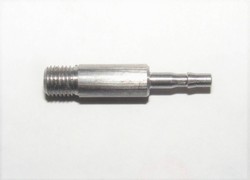
In order to connect the gas tube to the gas port an adaptor was made. This was a length of 6 mm steel that was single point threaded M6 fine at one end and turned down to 2.5 mm, the inner bore of the gas tube, at the other end. There was a barb turned that was 3 mm diameter about 4 mm from the end as shown.
The adaptor was drilled all the way through with a 1.5 mm hole
The adaptor was drilled all the way through with a 1.5 mm hole
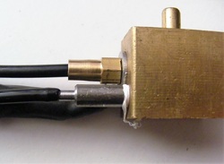
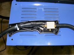
The adaptor was screwed into the brass block using PTFE tape to make a good seal. The gas tube fits tightly over the barb.
Once the gas tube was installed the torch trigger and body were reassembled.
Once the gas tube was installed the torch trigger and body were reassembled.
At the welder end the tube was passed through the deck of the wire feed compartment using the same hole as the welding cable. It was then routed along the side of the transformer and out the back of the welder through a grommetted hole.
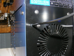
A discarded stainless steel container, originally a toilet brush holder, was used to support the gas cylinder. This was fixed to the back of the welder using long screws and two standoffs.
The standoffs are required to allow the lid of the wirefeed compartment to be opened.
The long screws go through two already existing holes that are used to mount the turbo fan inside the welder.
The standoffs are required to allow the lid of the wirefeed compartment to be opened.
The long screws go through two already existing holes that are used to mount the turbo fan inside the welder.
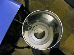
The cylinder is a loose fit in the container.
To stop it rattling around a polystyrene ring was cut and put in the bottom of the container.
To stop it rattling around a polystyrene ring was cut and put in the bottom of the container.
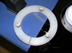
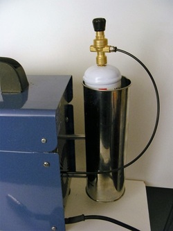
A plastic ring was also cut with three projecting studs. This slips over the top of the cylinder and the studs stabilise the top of the cylinder in the container.
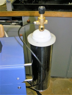
The finished cylinder support.
Modification to the electrics
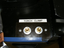
A terminal block was constructed on the deck of the wirefeed compartment. This was constructed so that the two M6 brass screws were insulated from the deck.
The terminal block is at the top right of this photo. The earth clamp and the welding torch attach to the underside of the two brass screws of the terminal block.
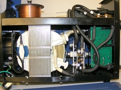
The vertical plates to the right of the transformer are the cooling fins for the rectifier diodes. They are also the connection points for the rectified output. The positive lead is attached to the bottom of the right hand plate. The negative lead connects to the top of the left hand plate. Both leads are 16 mm welding cable. The other ends of the lead pass through grommetted holes in the deck.
The vertical plates to the right of the transformer are the cooling fins for the rectifier diodes. They are also the connection points for the rectified output. The positive lead is attached to the bottom of the right hand plate. The negative lead connects to the top of the left hand plate. Both leads are 16 mm welding cable. The other ends of the lead pass through grommetted holes in the deck.
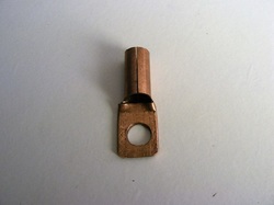
Connections above and below the deck are made using crimp on lugs. These can be bought but I had some 3/8" copper tube and it was easy to make as shown here.
Before crimping the lugs heat shrink tube was placed on the cable. After crimping the heat shrink was placed over the crimp and shrunk down using a hot air gun
Before crimping the lugs heat shrink tube was placed on the cable. After crimping the heat shrink was placed over the crimp and shrunk down using a hot air gun
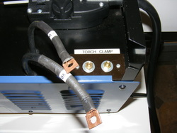
The finished cables seen from the top of the deck. They are labelled +ve and -ve. The terminals are labelled earth and torch and connections can be made so that the torch can have either polarity.
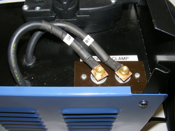
Here they are shown connected for with gas welding with the positive connected to the torch and the negative to the earth clamp.
The modified unit seems to perform well.
