Mill table stops and locks
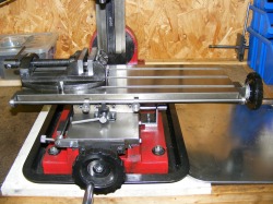
The Sieg X1 mill is one of the smallest and cheapest mills on the market. As such it is somewhat basic but it is capable of good work if you work within the limitations of the machine. It has two annoying features. The first is the absence of any system to provide a positive stop in both directions of the mill table. This makes cutting slots of a fixed dimension rather tedious as it is necessary to rely on the graduated collars on the handles. The second annoying feature is that the locking mechaniism for the x and y direction are small M4 socket head screws that lock the gibs. The left/right lock is easily accessible since it is on the front of the machine but the forward/back locking screw is underneath the table and is very difficult to get at. Furthermore, whenever it was necessary to lock the table then the correct hex key always seemed to be missing.
These problems have been solved by adding a rail on each axis of the table with sliding stops that can be locked to the rail. In addition the M4 locking screws have been replaced by levers that are much easier to operate.
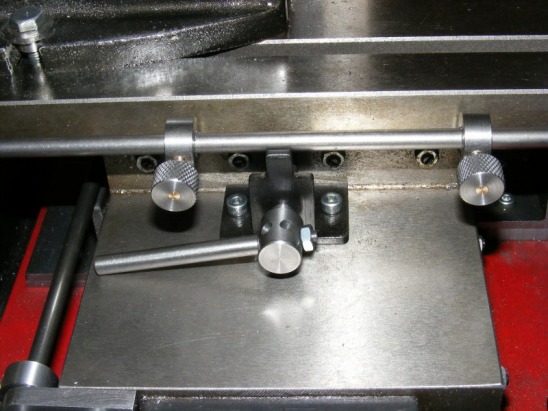
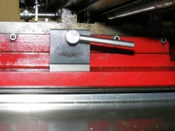
The header photo shows the arrangement on the left/right axis. A stop bar has been added to the front of the table. On the bar are two sliding stops that can be locked anywhere along the mill table. A stop block, made from a small piece of steel angle, is secured to the lower slide and this also supports the new lever operated locking screw. The hub for the lever has been drilled and tapped radially at 6 places for the lever so that it can be easily set to a position that provides locking by a 180 degree swing of the lever.
These problems have been solved by adding a rail on each axis of the table with sliding stops that can be locked to the rail. In addition the M4 locking screws have been replaced by levers that are much easier to operate.
The header photo shows the arrangement on the left/right axis. A stop bar has been added to the front of the table. On the bar are two sliding stops that can be locked anywhere along the mill table. A stop block, made from a small piece of steel angle, is secured to the lower slide and this also supports the new lever operated locking screw. The hub for the lever has been drilled and tapped radially at 6 places for the lever so that it can be easily set to a position that provides locking by a 180 degree swing of the lever.
This photo shows the 6 mm diameter bar across the front of the table. It is attached to the table by a bracket at either end.
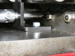
This shows the locking screw and stop block. The stop block is secured to the bottom slide by M4 screws.
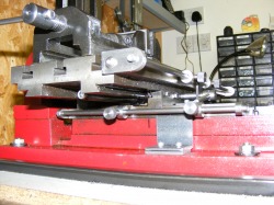
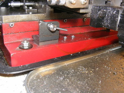
This photo is taken looking at the left hand side of the mill. The brackets supporting the front bar can be clearly seen. The brackets are attached to the mill table with M4 screws. Also shown in the photo is the stop bar attached to the lower (forward/back) slide. This is attached by brackets in the same way as for the front bar. The two sliding stops can also be seen as well as the stop block in the centre. This is a piece of steel angle bolted to the base of the mill with M4 screws.
This photo was taken from the right hand side of the mill and shows the support bracket and operating lever for the locking screw for the lower slide.
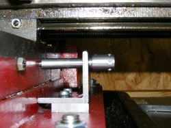
This shows the locking screw for the lower slide. The bracket is attached to the base of the mill with M4 screws, The hub of the locking lever is drilled and tapped for the locking lever in 6 places to permit the lever to be set so that locking occur within a 180 degree turn of the lever.
These very simple mods make the mill much more convenient to use.
Minor improvement to the original modification.
In the original version of the locking screw mod on the right hand side of the mill I placed the locking screw in the third gib screw hole. This was the position of the M4 cap lock screw that the manufacturer used. The new screw as shown above is much easier to use than the original but it is still right under the mill table.
Further examination showed that the screw can be moved to the second gib screw hole as shown. This puts it in an even more accessible position. In this position the dovetails are always engaged even if the table is wound in right up to the column.
It is not possible to move the lock screw to the first gib screw position because the two dovetails are dis-engaged at this position if the table is wound into up to the column
