New uses for an old grinder.
This project started because I needed to grind some carbide tooling. Normally I use HSS tooling and my bench grinder is set up with an aluminium oxide grinding wheel. My first thought was to buy a silicon carbide wheel for the bench grinder that could be used for grinding carbide. I then remembered that I had bought a diamond grinding disc in ALDI a while back. This should be able to grind carbide. I also remembered that I had an old 5 inch bench grinder that had been gathering dust for years. There was nothing wrong with the grinder and I stopped using it because it was difficult to find suitable 5 inch grinding wheels. Thus the first part of the project was to modify the grinder to take the diamond grinding disc and to provide a suitable grinding rest.
Having set up the diamond disc on the grinder I quickly realised that this set up would be ideal for sharpening drills using my Potts/Picador/ Reliance clone grinding jig. Previously in order to use the jig I had to remove all the guarding from by normal bench grinder and then attach the jig to the bench next to the grinder so that I could grind against the side of the grinding wheel. This was against all the conventions for safe use of grinding wheels since it could result in the grindstone shattering during use. Because of all the bother to set it up and the inherent danger the drill sharpening jig was rarely used. The diamond disc was metal and therefore unlikely to shatter and it was designed to be used on its face rather than on the edge. The second part of the project was to permanently mount the grinder and jig on a base board.
Having fitted the diamond disc and sharpening jig to the left hand side of the grinder I wondered what facilities I could add to the right hand side of the grinder. I already had a bench grinder set up for grinding HSS so I had no need for another grinding wheel. A soft wire brush would be quite useful on occasions for cleaning up rusty parts etc. I also note that many top class grinders had accessories for adding a chuck to the end of the spindle. The chuck could be used for a polishing mop or to drive a flexible drive. The final part of the project was to add these facilities to the right hand side of the grinder.
Part 1. The diamond disc grinder
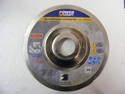
This is the diamond disc from ALDI. It is 115 mm diameter with a 22mm centre hole. It was designed for use in an angle grinder. It specifically states that it is for grinding steel and stainless steel. The othe side of the disc is covered with a layer of fine diamond grit.
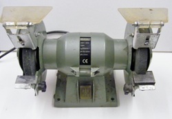
This is the old 5 inch bench grinder. It was in good condition but very dirty having spent at least 10 year stuck under a bench.
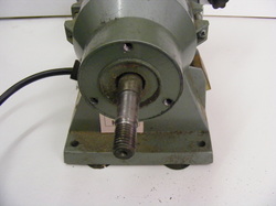
The fist job was to strip off the guards from the left hand side and remove the grinding wheel. The guards were attached to the motor body by three M6 screws. The bolt circle diameter was measured.
The spindle was 12.5 mm diameter and the end was threaded left hand M12.
The spindle was 12.5 mm diameter and the end was threaded left hand M12.
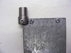
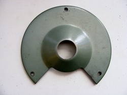
A new backplate was made from 2.5 mm steel sheet. This was 150 mm square with well rounded corners. The plate was attached to the motor with three M6 screws.
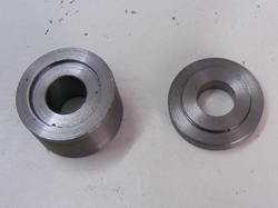
An arbour was made for the diamond disc from a piece of 32 mm diameter round steel. This was chucked in the lathe, faced, drilled 12.5 mm and a 1 mm male deep register 22 mm diameter was machined on the end. The end was then parted off 6 mm from the shoulder. The piece in the chuck was faced and a 1 mm female register turned to match the male register.
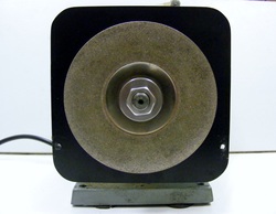
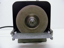
Using the arbour components the disc could be mounted on the grinder.
It was good to note that with the grinder on the disc was running true.
It was good to note that with the grinder on the disc was running true.
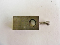
To support the grinding rest two support blocks were made from 10 x 20 steel. These was drilled our 10 mm diameter 27 mm from one end.
They were also drilled and tapped M4 in the centre of the left and right hand faces.
They were also drilled and tapped M4 in the centre of the left and right hand faces.
The rest was made from a piece of 2 mm sheet steel 50 mm x 150 mm.
Two pivots were machined from 12 mm round steel. This was turned down to 10 mm to fit the support blocks. The widest part of the pivot was milled down to provide a flat.. The flat was centre drilled for an M3 screw.
Two pivots were machined from 12 mm round steel. This was turned down to 10 mm to fit the support blocks. The widest part of the pivot was milled down to provide a flat.. The flat was centre drilled for an M3 screw.
The other side of the rest is supported on two 6 x 6 mm bars at each end.
The pivots were fitted into the support blocks and these were attached to the back plate using M4 screws.
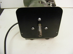
Two M4 cap screws were screwed into the threaded holes on the front of the support blocks. These screws can be tightened to lock the rest at any angle.
The back edge of the rest is close to the axis of rotation of the rest so that the edge keeps an almost constant distance from the disc.
Two M4 cap screws were screwed into the threaded holes on the front of the support blocks. These screws can be tightened to lock the rest at any angle.
The back edge of the rest is close to the axis of rotation of the rest so that the edge keeps an almost constant distance from the disc.
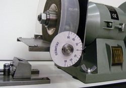
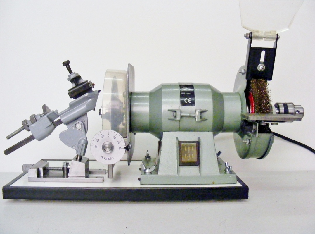
One of the pivots was made longer than the other so that it protrudes from the support block. An angular scale was attached here to indicate the position of the rest.
The scale was made from a 50 mm penny washer. This was drilled out 12 mm. A piece of 16 mm rod was face and drilled out 10 mm. The end was then turned down to 12 mm diameter for a distance of 1.5 mm so that it was a good fit in the central hole of the washer. The rod was parted of 6 mm from the end. The washer was placed on the end of the bush and a 90 degree hardened cone pressed into the end closest to the washer using the bench vice. This expands the end and locks the washer in place. The bush was cross drilled and tapped M3 for a grub screw so that it could be fixed to the protruding pivot.
The scale was drawn using a CAD program and printed out one self adhesive photo paper. This was then cut out and stuck to the washer.
Notice also in this photo that a polyethylene guard has been placed around the grinding disc. This is not for protection from the disc shattering but to prevent the possibility of grinding dust being thown into eyes. However, eye protection should always be worn when grinding. The guard was made from a cut down round food container. and it bolts onto the back plate using the same screws that hold the back plate to the motor
Part 2. Drill sharpening
This is the cheap clone of the Potts/Picador/Reliance jig that is readily available from a number of suppliers.
The build quality is not wonderful and the nasty plastic knurled nuts of the advance mechanism were replaced by metal components.
I never had any success with this jig as is because the axis of inclination is not sufficient. It needs to lean forward by 15 degrees.
The build quality is not wonderful and the nasty plastic knurled nuts of the advance mechanism were replaced by metal components.
I never had any success with this jig as is because the axis of inclination is not sufficient. It needs to lean forward by 15 degrees.
I made a new base that provided the 15 degree inclination.
With this modification then the drill jig works very well.
However, as pointed out in the introduction it was much hassle to adapt my usual bench grinder to sharpen drills and it was also a procedure that was potentially hazardous. For this reason the jig has not been used a great deal.
The diamond disc grinder is much better suited for use with this jig.
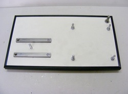
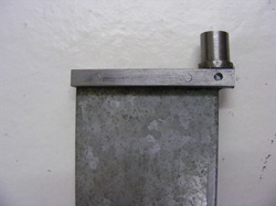
A baseboard was made up from 15 mm laminated chipboard.
The four screws on the right hand side are for the diamond disc grinder.
The two metal guides on the left hand side are for the drill sharpening jig. The screw between the guides is for clamping the jig down.
The four screws on the right hand side are for the diamond disc grinder.
The two metal guides on the left hand side are for the drill sharpening jig. The screw between the guides is for clamping the jig down.
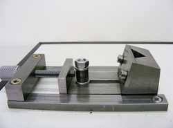
The base has been modified as shown here. This provides a controlled method of advancing the base of the jig towards the diamond disc. A vertical plate was attached to the rear of the base using two M3 screws. This is drilled M6 for the feed screw.
Turning the knurled knob one revolution advances or retracts the base by 1 mm.
The locking nut in the middle is raised by a collar so that the nut can be tightened without hitting the feed screw
Turning the knurled knob one revolution advances or retracts the base by 1 mm.
The locking nut in the middle is raised by a collar so that the nut can be tightened without hitting the feed screw
The feed screw is a length of M6 studding. This was turned down to 4 mm for a length of 25 mm and the last 13 mm was threaded M4.
The square bar was drilled out 4 mm and the feed screw passed through.
The knurled knob is drilled out and tapped M4.
The knurled nut screwed on to the feed screw so that there is little longitudinal play but the feed screw can still turn easily. The knob is then locked onto the feed screw using an M4 grub screw in the end of the knob.
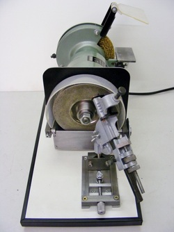
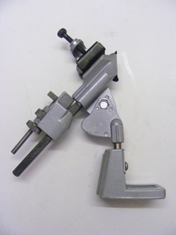
This shows the set up for drill sharpening.
Note that the grinding rest is folded down and does not interfere with the movement of the drill grinding jig.
Note that the grinding rest is folded down and does not interfere with the movement of the drill grinding jig.
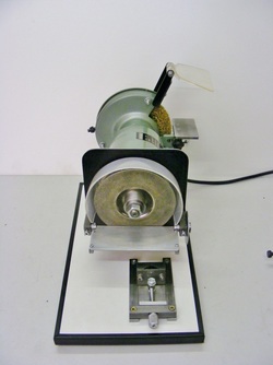
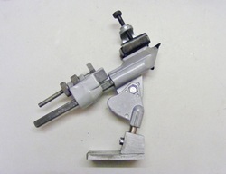
This shows the set up for grinding carbide tools.
Not that the sharpening jig has been removed and the grinding rest swung up. The jig base does not interfere with the movement of the grinding rest.
Not that the sharpening jig has been removed and the grinding rest swung up. The jig base does not interfere with the movement of the grinding rest.
Part 3. Wire brush and chuck.
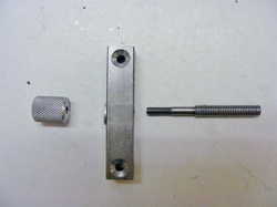
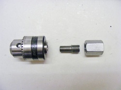
These are the parts for the addition of a wire brush and a chuck on the right hand side of the grinder.
One the left is an M12 connector nut. This is a 40 mm long nut threaded M12 that is used to join lenths of threaded rod together.
The chuck was a 1-10 mm chuck that was in the scrap box. It was threaded 3/8 x 24 tpi.
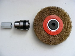
The wire brush is 125 mm diameter and it was bought on ebay. It was supplied with adaptors for 1/2" and 5/8" shafts.
One the left is an M12 connector nut. This is a 40 mm long nut threaded M12 that is used to join lenths of threaded rod together.
The chuck was a 1-10 mm chuck that was in the scrap box. It was threaded 3/8 x 24 tpi.
The wire brush is 125 mm diameter and it was bought on ebay. It was supplied with adaptors for 1/2" and 5/8" shafts.
A 28 mm hole was drilled through the guard for the chuck to protrude through. A step drill was used to make the hole.
The wire brush, with the 1/2" adaptors, was mounted between two washers onto the motor shaft.
The connector nut was faced in the lathe on one end. The faced end was then screwed on tight to bed the adaptors onto the brush. The distance of the end of the shaft from the end of the nut was measured. The nut was then removed and cut down and faced to leave a 14 mm gap between the end of the shaft and the end of the nut. The nut was then n screwed back on the shaft
The guard was the replaced onto the grinder.
An adaptor was made from 1/2" round bar. This was turned down to 3/8" for a distance of 16 mm. The bar was turned down to 12 mm for a further distance of 12 mm. Run out grooves were then made at the shoulder and at the end of the 12 mm section. The 3/8" section was single point threaded 24 tpi and the 12 mm section threaded 1.75 mm pitch in the same way. All turning and threading operation were made without removing the bar from the chuck to ensure concentricity.
The threaded adaptor was screwed hard onto the drill chuck and the other end onto the connector nut.
The threaded adaptor was screwed hard onto the drill chuck and the other end onto the connector nut.
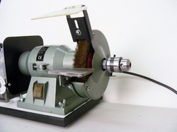
This shows the right hand side of the grinder with all the modifications.
Note- rapidly rotating wire brushes can be dangerous. They can throw out bristles at high velocity with sufficient momentum to penetrate clothing or skin. Always wear eye protection and stout gloves.
Note- rapidly rotating wire brushes can be dangerous. They can throw out bristles at high velocity with sufficient momentum to penetrate clothing or skin. Always wear eye protection and stout gloves.
