Tailstock turret
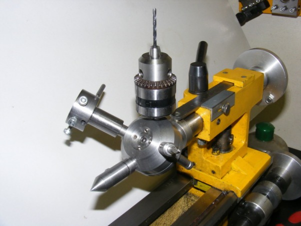
A tailstock turret is a useful addition to the lathe and it can save much time changing tools in the tailstock. The turret shown above is easily constructed and carries four tools: a rotating centre, a chuck, a centre drill and a die holder. Of course other tools could be made for the turret, if needed, since the individual tools are interchangeable.
There are five main components to the turret: the taper, the base plate, the turret block, the pivot pin and the detent assembly.
There are five main components to the turret: the taper, the base plate, the turret block, the pivot pin and the detent assembly.
This photo shows the taper. It was machined from 19 mm round stock and cut off at an angle of 45 degrees using the bandsaw. The centre was located by plugging the taper into the headstock using an MT2-MT3 adaptor and then bringing a small conical burr into contact with the rotating piece. An M4 threaded hole was then drilled and tapped through the centre perpendicular to the flat face, as shown.
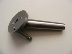
The base plate is shown attached to the taper. Also shown in the photo is the detent assembly with the detent pin protrudig from the face of the base plate. The base plate is 50 mm diameter and 6 mm thick. The centre is drilled out to 8 mm. The plate is secured to the taper by epoxy resin and two M3 countersunk screws that are visible either side of the central hole. This "glued and screwed" attachment method has proven completely satisfactory because the forces acting on the joint are axial compression and the resulting shear force about the inclined plane. This is perfect for an adhesive bond since no tensile or peeling forces are acting.
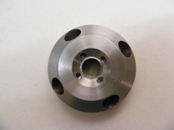
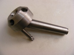
This shows the completed turret block. It was machined from a piece of 50 mm diameter x 19 mm round stock. The central hole is drilled out 8 mm and counterbored out to 10 mm for the pivot pin. The male and female conical sections are both machined at 45 degrees. The large outer ring of holes are 10 mm diameter to accept the tools and the inner ring of holes are drilled and tapped M4 for the tool clamping screws. The outer and inner ring holes are only drilled once the whole unit is assembled on the base plate with the detent ( see later).
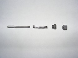
This shows the internal components of the detent mechanism. The detent pin is 4 mm diameter and the shaft is 3 mm diameter and threaded M3 at the end. The spring was recovered from a ball point pen. The closure is machined from 8 mm round stock and is threaded M6. The last component is the actuating knob which is tapped internally to M3. These components fit in a tube machined from 8 mm stock. This is drilled through M4 and then bored out partially to M5 and threaded internally at the end to M6. The end with the 4 mm hole is threaded externally M8 and screws into the base plate as shown in the earlier photo of the baseplate.
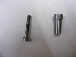
This is a photo of the pivot pin and screw. The pin is machined from 10 mm round stock. It is drilled out to accept the M4 screw. The pivot pin passes through the turret block into the base plate hole and the M4 screw then secures it to the taper.
This shows the completed turret after assembly.
The most critical thing in making this turret is to make and fit the components together in the right order.
The steps involved are as follows:
1. Make the taper, cut the diagonal, find the centre and drill and tap to M4.
2. Make the base plate and turret block. These should be bored through 8 mm centrally and the turret block counterbored to 10 mm. Do not drill any other holes other than these central holes at this stage.
3. Machine the pivot pin to be a close fit in the bore of the base plate and turret block.
4. Use the pivot pin to centralise the base plate to the tapped hole in the taper. Then drill, tap and countersink the M3 holes for the screws that hold the base plate to the taper. Degrease the taper and base plate and apply epoxy resin to the joint surfaces and then assemble together using the M3 screws. Before the epoxy sets remove the pivot pin.
5. Drill and tap the base plate M8 for the detent mechanism.
6. Make the detent mechanism tube and screw it into the base plate.
7. Assemble the turret block to the base plate using the pivot pin. Drill though the detent tube into the turret block with an M4 drill. Then rotate the turret through 90 degrees and drill a second hole. Repeat this until four holes have been drilled into the turret block at 90 degree intervals.
8. Machine the detent pin to an exact sliding fit in the detent tube and the holes in the turret block. Then make the rest of the detent components. Assembly the detent mechanism. The turret block should now be able to rotate when the pin is withdrawn and then click into place at four positions on the turret block.
9. Check the alignment of the tailstock and push the taper into the tailstock. With a centre drill in the lathe chuck, mark the positions for the holes for the tools at each of the four positions where the detent locates. Then drill the 10 mm holes for the tools. This ensures that the holes are exactly on the lathe axis.
10. The final operation is to drill and tap the M4 holes for the clamping screws. To do this mount a piece of 10 mm bar horizontally in the drill vice with 15 mm protruding. Push each of the tool holes onto the bar and then drill down through the inner conical face with a 4 mm tapping drill. Tap the holes to M4.
Following this procedure ensures that all the components line up properly, that all the tool holes are on the lathe axis and that the clamping screws are correctly positioned.
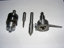
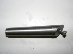
This shows the tools made to go in the turret. The chuck is a 10 mm chuck. This had a 3/8" UNF female thread. A piece of 12 mm stock was machined down to an exact fit in the tool hole of the turret and then single point threaded until the chuck was a close fit. The bar was parted off and a small flat for the clamp screw milled on the shank. The centre drill holder was made in a similar way by machining some 12 mm stock to a good fit in the turret tool hole. It was then bored to accept the centre drill and cross drilled for a small M3 clamping screw. The centre was constructed in the same way as described in the section on revolving centres. The tailstock die holder is just a piece of bar machined to fit the turret hole with a sliding die holder turned from 38 mm stock.
The only problem with this turret is that it is difficult to use in conjunction with the rear tool post since the tools not in use tend to conflict with it. I really need a longer cross slide (another 25 mm) to be able to make full use of the tailstock turret/ rear toolpost combination. Yet another project!!
