Tangential tool flycutter.
I made a tangential toolholder for the lathe some time ago. I use this frequently and I have always been impressed by the rate of metal removal possible with this tool. Cuts of 0.5 mm are routine cuts of 1 mm are possible.
There was a discussion recently on the madmodder site initiated by Andrew Franks (http://madmodder.net/index.php?PHPSESSID=210d39190706cf3af771109f3ca80f01&topic4301.0) on designing flycutters. This prompted me to think about flycutter design. On my little X1 mill the depth of cut possible using a flycutter was very limited, typically about 0.1 mm. I started to wonder whether a flycutter with a tangential tool was possible and whether it would increase the rate of removal of material. After playing about with the idea in my mind I sat down at the computer and started to design a tool using CAD. The tool here is the result.
There was a discussion recently on the madmodder site initiated by Andrew Franks (http://madmodder.net/index.php?PHPSESSID=210d39190706cf3af771109f3ca80f01&topic4301.0) on designing flycutters. This prompted me to think about flycutter design. On my little X1 mill the depth of cut possible using a flycutter was very limited, typically about 0.1 mm. I started to wonder whether a flycutter with a tangential tool was possible and whether it would increase the rate of removal of material. After playing about with the idea in my mind I sat down at the computer and started to design a tool using CAD. The tool here is the result.
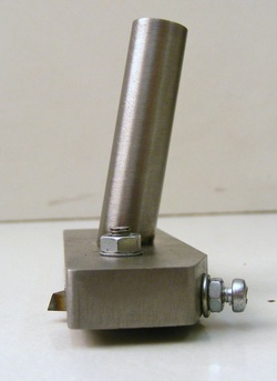
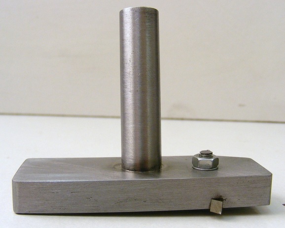
Following the same design criteria for a tangential lathe tool holder the tool is inclined at 12 degrees to the surface being cut. This is achieved by angling the flycutter shaft at 12 degrees to the tool holder base as shown here.
The base is a length of 10 x 25 mm steel flat 73 mm long. This was drilled out for the 12 mm shaft. The drilling operation was tricky. First the hole must be positioned so that it passes through the centre of the bar in order that it is balanced. This means that the starting point for the hole on the top surface is slightly (1mm) off centre. The start point was marked out and then the piece set up in the mill vice at a 12 degree angle. The setting up was done by using a 5 mm drill to lift one side of the bar to the correct angle (5 mm in 25 mm slope corresponds to 12 degrees). At the marked point a centre drill was used to open out a small starting hole. The bar was then drilled through 3 mm. A larger centre drill was then used to open out the lead in to this hole and it was drilled out to 6 mm. This was continued until the hole was opened out in successive stages to 12 mm. In the latter stages 90 degree countersink bit were used as centre drills. The reason for this complex procedure is that drilling at an angle tends to deflect the drill and without the succesive use of drills and centre drillls the hole will wander a long way from its initial starting position. An alternative might have been to use a 12 mm slot drill to open out a flat bottomed hole for drilling.
The base is a length of 10 x 25 mm steel flat 73 mm long. This was drilled out for the 12 mm shaft. The drilling operation was tricky. First the hole must be positioned so that it passes through the centre of the bar in order that it is balanced. This means that the starting point for the hole on the top surface is slightly (1mm) off centre. The start point was marked out and then the piece set up in the mill vice at a 12 degree angle. The setting up was done by using a 5 mm drill to lift one side of the bar to the correct angle (5 mm in 25 mm slope corresponds to 12 degrees). At the marked point a centre drill was used to open out a small starting hole. The bar was then drilled through 3 mm. A larger centre drill was then used to open out the lead in to this hole and it was drilled out to 6 mm. This was continued until the hole was opened out in successive stages to 12 mm. In the latter stages 90 degree countersink bit were used as centre drills. The reason for this complex procedure is that drilling at an angle tends to deflect the drill and without the succesive use of drills and centre drillls the hole will wander a long way from its initial starting position. An alternative might have been to use a 12 mm slot drill to open out a flat bottomed hole for drilling.
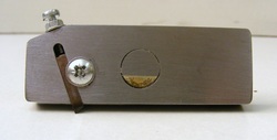
The underside is slotted to receive the 1/8" square tool. The slot is slightly less deep than the tool so that it can be clamped under the M4 screw head as shown. The small M3 screw at the top of the photo is a stop to prevent the tool hammering back in the slot during intermittent cuts. It is also used to adjust the protrusion of the tool. The shaft has been silver soldered into the central hole. The angle of the slot is such that it is 12 degrees less than than a tangent to the circle that is centred on the axis of rotation passing through the tip of the tool.
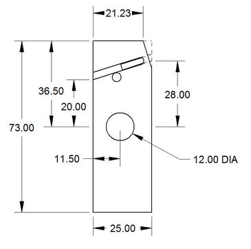
The tool of the flycutter is designed to sweep through a circle of 50 mm diameter. The dimensions and features of the base plate are shown in this drawing.
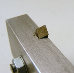
The tip of the tool is ground at a 30 degree angle. This is exactly the same as for my tangential lathe tool holder and a grinding jig is shown here.
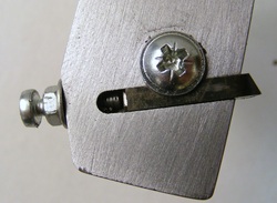
A close up of the tool, clamping screw and the end stop screw.
The benefit of this tangential tool flycutter is that it can take much larger cuts than a conventional tool. In tests flycutting of EN3 steel I can remove at least 0.4 mm in one pass without the mill showing any stress. With a conventional flycutter the mill would be struggling with a cut of 0.15 mm. The only downside to the tool seems to be that it is difficult to get cutting fluid to the surface being cut but by generously flooding the surface with cutting fluid before the start this can be overcome.
In addition, the surface finish that is achievable is much better than with my conventional flycutters. I think in part this is because the attack angle of the tangential tool is at a very low angle to the workpiece surface.
In addition, the surface finish that is achievable is much better than with my conventional flycutters. I think in part this is because the attack angle of the tangential tool is at a very low angle to the workpiece surface.
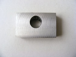
This photo is of a block of steel flycut using the tool. The speed of the tool was 100 rpm and the feedrate was 30 mm/min. The surface is very smooth with no roughness.
Designing tangential tool flycutters
It is relatively easy to design a tangential tool flycutter that will sweep through a circle of any specified diameter.
The angle of the plate with respect to the rotating shaft is set by drilling the plate at an angle as described above. The angle that I have used is 12 degrees. The only reason for choosing this angle was because this is what I had previously used for my lathe tangential toolholder.
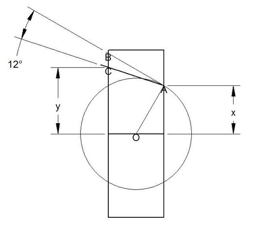
The drawing above shows how to calculate the position of the tool slot in the base plate. First choose the size of the base plate and select the centre point O. Now draw a circle of diameter equal to the desired swept circle of the cutter. This circle intercepts the base plate at point A. Draw the tangent AB to the circle at this point. Now draw another line, AC, at 12 degrees from the tangent as shown. This line marks the edge of the tool slot. Measure the distances x and y on the diagram and use these to mark out the base plate.
