Taper turning attachment
A number of modifications to the top slide have been shown in an earlier section that improve the cutting of tapers on the minilathe. With these modifications it is relatively easy to turn MT2 tapers. However any taper longer than about 80 mm is beyond the capacity of even the modified top slide. For longer tapers then some sort of taper turning attachment is desirable. Another advantage of using a taper turning attachment is that the lathe autofeed can be used and this results in a better surface finish on the final taper.
.All the published designs (that I can find) for taper turning attachments on the minilathe bolt onto the back of the lathe bed casting. This is inconvenient, especially with an extended cross slide, since they may interfere with each other. Mounting and dismounting such a unit is difficult since access to the rear of my lathe is limited.
The following criteria were used as a basis for the design of the taper attachment descibed here:
1. The unit should be easy to mount and dismount from the lathe.
2. The installation of the attachment should not require the removal of the chip guard.
3. It should incorporate an easy way of setting the taper angle.
4. There should be some indication of the set taper angle.
5. It should be capable of being used in conjuction with the tailstock.
6. It should have a range of about 8 degrees in either direction.
7. It should be easy to set up.
The present unit meets these criteria. It differs from other published designs in that it attaches directly on top of the lathe bed ways and that it incorporate a worm to adjust the taper angle.
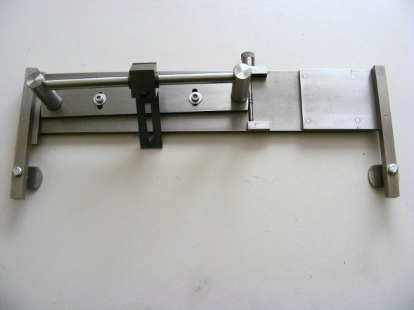
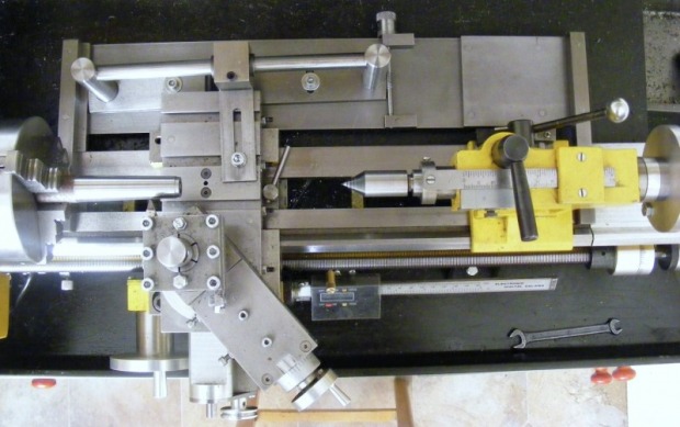
The header picture shows the completed unit. It consists of several main components.There is a base plate made from 6 x 75 mm steel flat. This is attached to the lathe bed ways by two 12 mm square bars at each end. These are clamped to the ways by two M6 bolts and nuts that fit the gap between the ways. On the base plate is mounted the swivel plate made from 6 x 35 mm steel flat. This is pivoted close to the middle and it carries two 19 mm diameter steel pillars that support a length of 12 mm precision ground, round steel bar. On the bar is a follower with cast iron bearings that connects to the cross slide. With the cross slide free to move (ie uncoupled from the cross slide handle) it will then follow what ever angle the guide bar is set to. The angle is set by means of a worm located at the left hand end of the swivel plate. This worm has a collar that is graduated with fifty divisions allowing setting of the angle with a precision of 0.01 degrees. There are also two clamp bolts that run in circular slots on the swivel plate. These are used to lock the setting of swivel plate once the angle is set. The right hand end of the swivel plate is graduated with a scale marked in one degree intervals.
.All the published designs (that I can find) for taper turning attachments on the minilathe bolt onto the back of the lathe bed casting. This is inconvenient, especially with an extended cross slide, since they may interfere with each other. Mounting and dismounting such a unit is difficult since access to the rear of my lathe is limited.
The following criteria were used as a basis for the design of the taper attachment descibed here:
1. The unit should be easy to mount and dismount from the lathe.
2. The installation of the attachment should not require the removal of the chip guard.
3. It should incorporate an easy way of setting the taper angle.
4. There should be some indication of the set taper angle.
5. It should be capable of being used in conjuction with the tailstock.
6. It should have a range of about 8 degrees in either direction.
7. It should be easy to set up.
The present unit meets these criteria. It differs from other published designs in that it attaches directly on top of the lathe bed ways and that it incorporate a worm to adjust the taper angle.
The header picture shows the completed unit. It consists of several main components.There is a base plate made from 6 x 75 mm steel flat. This is attached to the lathe bed ways by two 12 mm square bars at each end. These are clamped to the ways by two M6 bolts and nuts that fit the gap between the ways. On the base plate is mounted the swivel plate made from 6 x 35 mm steel flat. This is pivoted close to the middle and it carries two 19 mm diameter steel pillars that support a length of 12 mm precision ground, round steel bar. On the bar is a follower with cast iron bearings that connects to the cross slide. With the cross slide free to move (ie uncoupled from the cross slide handle) it will then follow what ever angle the guide bar is set to. The angle is set by means of a worm located at the left hand end of the swivel plate. This worm has a collar that is graduated with fifty divisions allowing setting of the angle with a precision of 0.01 degrees. There are also two clamp bolts that run in circular slots on the swivel plate. These are used to lock the setting of swivel plate once the angle is set. The right hand end of the swivel plate is graduated with a scale marked in one degree intervals.
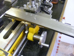
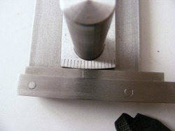
This picture shows the set up for cutting the gear on the end of the swivel plate. A 6 mm hole was drilled at 115.5 mm from the end of the swivel plate on the centre line of the bar. The bar was then machined, using the mill and rotary table, to a radius of 115.5 mm. A plate with a pivot pin was clamped in the lathe toolholder and the swivel plate placed over the pivot pin as shown in the photo. On the left of the picture can be seen a standard M6 tap held directly in the lathe chuck. The axis of the tap is centred on the end of the bar. The gear is cut by slowly advancing the plate until it contacts the tap. The swivel plate is free to rotate on the pivot plate and as the tap cuts then the plate moves round following the pitch of the tap. Light cuts are taken, slowly advancing the plate into the tap. The swivel plate was advanced 1.2 mm into the tap to cut the gear. Periodically the swivel plate was turned over in order to ensure a symettrical thread. During these operations the pivot plate, the pivot and the tap were kept well lubricated.
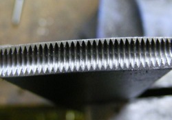
This photo shows the finished gear after cutting. The teeth are well formed and of accurate pitch. This was quite surprising because cutting gears by this "free hobbing" technique has been much criticised. I think it worked so well in this instance because the gear radius is large and therefore the drag torque is correspondingly low.
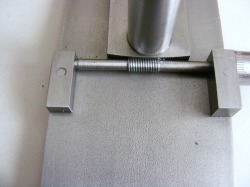
This photo shows a detailed view of the worm. This was made from a piece of M6 studding turned down to 5 mm either side of the threaded portion. The ends are turned down to 4 mm and fit into the small bearing blocks. The left hand block was 6 x 10 x 25 mm and the right hand one was 6 x 10 x 12 mm
The blocks are attached to the base plate with M4 screws. On the right hand side the 4 mm spindle protrudes circa 12 mm and is threaded M4 for a distance of 14 mm. The knurled graduated adjuster knob screws on the protruding thread and it is adjusted to minimise the end play between the knob and the bearing block and then locked in place with a grub screw.
The blocks are attached to the base plate with M4 screws. On the right hand side the 4 mm spindle protrudes circa 12 mm and is threaded M4 for a distance of 14 mm. The knurled graduated adjuster knob screws on the protruding thread and it is adjusted to minimise the end play between the knob and the bearing block and then locked in place with a grub screw.
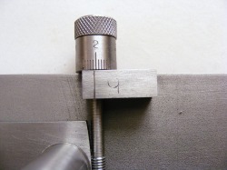
Here is a close up of the adjuster knob. The knob has a graduated friction collar so that it can be set to zero. Friction is provided by an O ring in a groove under the graduated collar. The collar is graduated with 50 divisions. Each complete turn of the knob alters the angle by 0.5 degrees so that each division represents 0.01 degrees.
This photo shows the degree markings at the other end of the swivel plate. Note the spacer between the clamp bar and the base plate. This serves three functions. It lowers the base plate by 6 mm, it provide a place for marking the index line against which the graduations are read and the end of the spacer is also used to set the distance of the base plate from the lathe way.
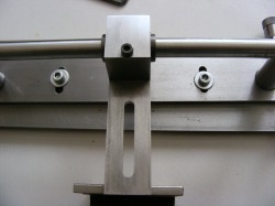
This photo shows the follower slide that runs on the precision ground guide bar. The follower block is made from a piece of 25 x 25 x 30 mm mild steel. The block has been bored out to 16 mm and a cast iron sleeve inserted to reduce friction. Epoxy resin was used to fix the sleeve in the block. The sleeve was bored out to be a good sliding fit on the bar. My original intention was to then slit the bllock and add a clamp screw so that the bearing could be adjusted to achieve an optimum fit. However, the fit on the bar was very good as bored so this was not necessary. The block is attached to a slotted strip of 3 x 25 mm mild steel. This is bolted to the cross slide through the slot, which allows some positional adjustment. The two clamping screws under the bar can be clearly seen in this photo. These are tightened once the angle of the bar has been set to lock the bar to the base plate.
This photo shows the attachment clamped to the lathe bed and set up for cutting an MT2 Morse taper. The handle of the cross slide feed screw has been removed so that the cross slide can slide freely. The cross slide has been attached to the follower slide and the angle of the bar has been set to the morse taper angle. The top slide has been set over to about 45 degrees. The top slide is used to increment the cut at each pass. Note on the left hand side of the unit the spacer between the clamping bar and the base plate has been pushed hard against the back edge of the lathe way. This sets the position of the attachment at the headstock end.
Setting up the attachment on the lathe is fairly straightforward:
1. Adjusting the guide bar parallel to the ways.
First adjust the unit so that the swivel plate is set to zero degrees and the graduated collar is set to zero and clamp the swivel plate to the base plate. Now clamp the attachment roughly parallel to the lathe bed making sure that the end of the spacer is in contact with the back edge of the rear way. Move the carriage to the head stock end and attach the follower arm to the cross slide. Clamp the cross slide by tightening one of the gib screws. Now loosen the tailstock end clamping screw and slide the carriage towards the tailstock and retighten the clamp screw. This precedure sets the guide bar parallel to the lathe ways. Check that the carriage can traverse the whole length of the unit without binding and if necessary readjust. Then release the gib screw used to lock the cross slide.
2. Remove the feed screw from the cross slide.
On a standard lathe this can be done by removing the handle and graduated collar. Undo the the two screws holding the thrust collar to the cross slide and remove this. Now the feed screw can be unscrewed. On my modified cross slide it is only necessary to remove the the handle and graduated collar and then screw the feed screw in a little to provide free movement of the cross slide.
3. Setting the taper angle.
Loosen the screw holding the follower arm to the cross slide and then loosen the two clamping screws on the swivel plate and use the knob to set the required angle. Once the angle is set then tighten the swivel plate clamping screws and the follower arm screw. Check that the carriage moves freely and that the cross slide is following the angle of the guide bar.
4. Chuck the work piece.
Chuck the work piece and check that there is sufficient movement of the cross slide to cut the taper. If there is insufficient then loosen the screw securing the follower arm to the cross slide and push or pull the cross slide to a better position and then retighten the screw.
5 Cut the taper.
Using the top slide wind the tool in to the start of the taper. Start the lathe and use autofeed to take a light cut (0.25 mm or less). Repeat the cutting passes until the taper is cut.
