USB microscope/shadowgraph
This project was inspired by a video that Malcolm Parker Lisberg posted on YouTube (http://www.youtube.com/watch?v=lw1b58kITxQ&feature=youtu.be). Malcolm's version was made using aluminium castings and incorporated a very neat rack and pinion height adjuster. My version was constructed without using castings.
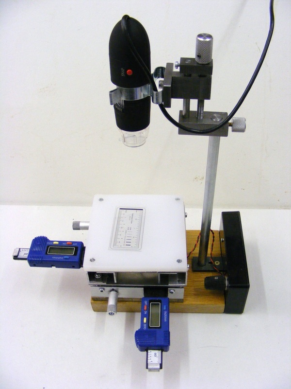
The unit consists of a cheap USB microscope (circa £14 on ebay from Hong Kong) mounted on a stand. Under the stand is a microscope stage which can be moved along two axes independently. The movement of the stage is controlled by a leadscrew in each direction and the movement is measured by two digital tyre depth gauges (circa £4 each on ebay) to an accuracy of 0.01 mm. The microscope has built in illumination from 8 LEDs. The stage can also be backlit allowing the unit to be used as a shadowgraph.
The unit consists of a cheap USB microscope (circa £14 on ebay from Hong Kong) mounted on a stand. Under the stand is a microscope stage which can be moved along two axes independently. The movement of the stage is controlled by a leadscrew in each direction and the movement is measured by two digital tyre depth gauges (circa £4 each on ebay) to an accuracy of 0.01 mm. The microscope has built in illumination from 8 LEDs. The stage can also be backlit allowing the unit to be used as a shadowgraph.
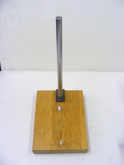
The stand consists of a block of oak 20 mm thick. This is drilled out 10 mm and a 10mm steel rod glued into the hole with epoxy resin. The rod protrudes 200 mm from the base
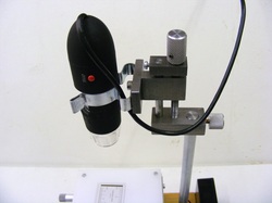
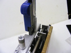
At the top of the column is the microscope. This is clipped into a Terry clip. The Terry clip is attached to a height adjuster mechanism. Coarse adjustment is by sliding he whole assembly up and down the rod and fine adjustment is by means of a screw.
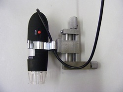
This shows the adjuster mechanism in more detail. At the bottom is a 10 mm base plate. The knurled knob on the right hand side is the clamping screw that fixes the adjuster at a suitable height on the stand rod.
The knurled knob at the top connects to a M6 leadscrew and this allows the middle block to be adjusted in height precisely. The rod on the right hand side prevents the middle block rotating
The knurled knob at the top connects to a M6 leadscrew and this allows the middle block to be adjusted in height precisely. The rod on the right hand side prevents the middle block rotating
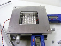
The top of the stage is covered with a piece of 9 mm thick polyethylene ( cut from a kitchen chopping board) which serves as a light diffuser. In this photo the diffuser has been removed to show the 36 LED array which is located just below the 100 mm square top plate. The LED array is attached to the top plate so that it is always directly below the aperture.
This shows the underside of the top plate. The LED array is affixed to the two brackets in the middle of the photo using the double sided adhesive tape supplied with the array . The whole assembly slides on rods that pass through the two outermost sets of holes either side of the LED array. The aluminium rails are made from 3/4" x 1/16" aluminium angle.
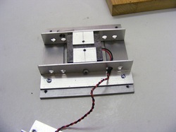
This shows the other side of the top plate assembly. Note the oblong grey block on the front rail. This is bored 5 mm and tapped M6 for the leadsrew.
The top plate assembly slides on the two 6mm rods shown in this photo. Also shown is the M6 leadscrew with it's knurled adjuster knob and the tyre depth gauge that measures the movement.
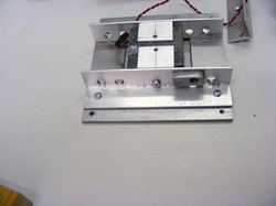
Once the top plate has been slid on the 6 mm rods the piece of angle on the left hand side is screwed to the ends of the rods and to the bottom plate.
The push rod of the tyre gauge pushes against the aluminium angle attached to the top plate.
Once the top plate has been slid on the 6 mm rods the piece of angle on the left hand side is screwed to the ends of the rods and to the bottom plate.
The push rod of the tyre gauge pushes against the aluminium angle attached to the top plate.
The tyre gauges are fitted with springs to ensure that they always press against the aluminium angle.
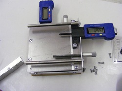
Beneath this top stage is another that moves at right angles to the top stage. The constuction of this is identical to the top stage but without the LED array and brackets
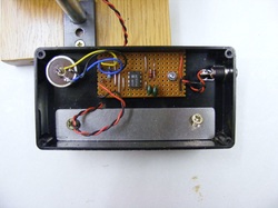
The black box at the back of the unit houses a circuit that varies the intensity of the light from the LED array. This is a simple pulse width modulator based on a 555 timer that varies the pulse duration from 5% to 95%. The potentiometer at the top left sets the pulse duration and 12V dc is supplied to the socket on the right.
The microscope is supplied with some software that enables direct measurement of distances and angles on the screen. Accurate measurements are better carried out using the digital tyre guages.
I envisage that this instument will be useful for inspecting cutting tools, measuring gears, determining thread forms etc.
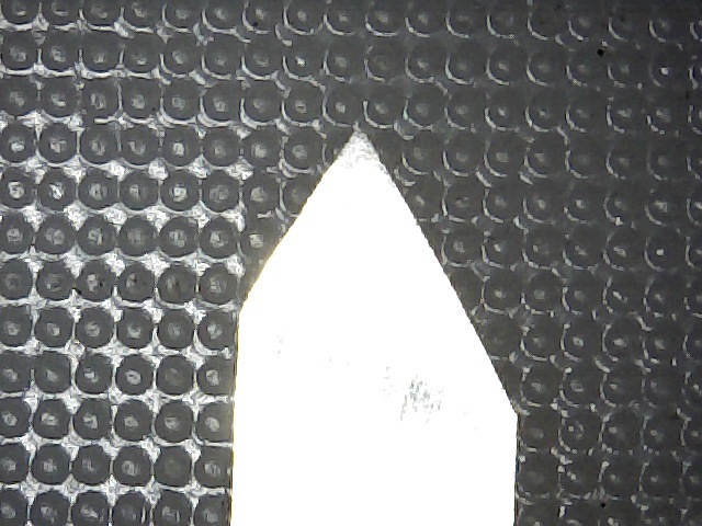
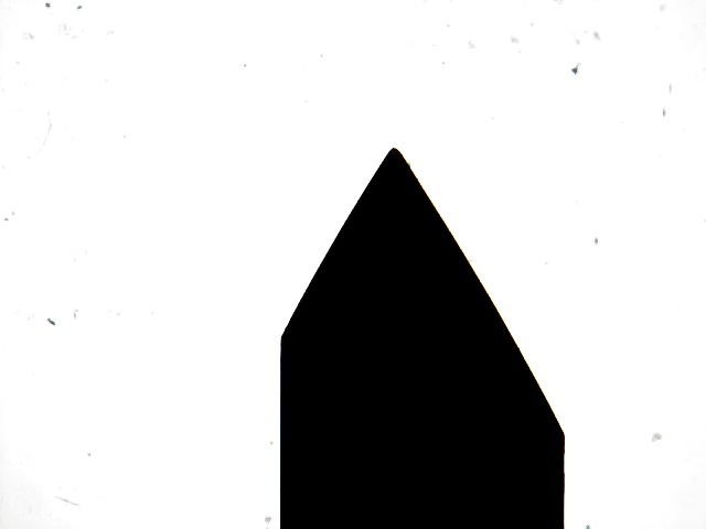
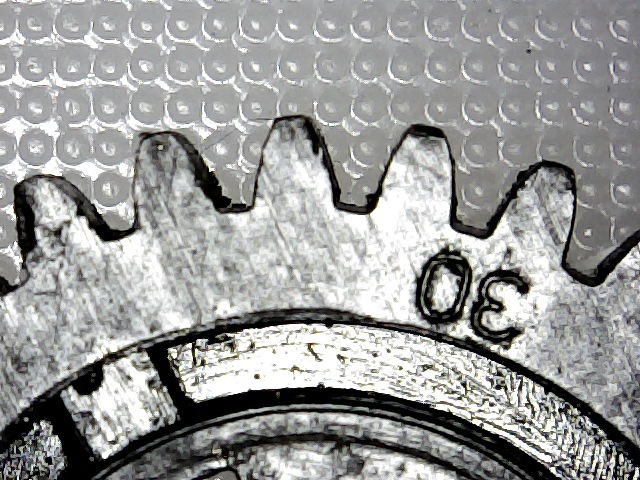
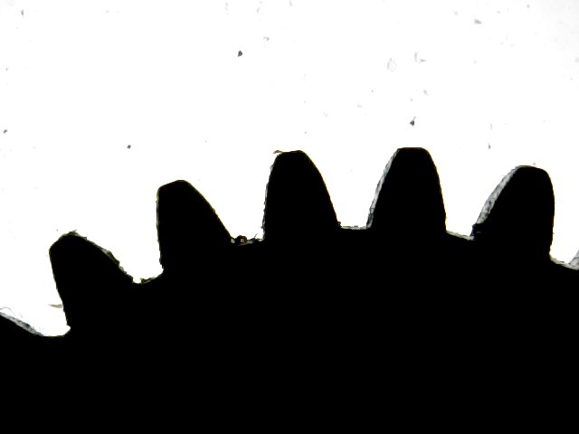
The following images illustrate the differences between incident light microscopy and back light (shadowgraph) microscopy
I envisage that this instument will be useful for inspecting cutting tools, measuring gears, determining thread forms etc.
The following images illustrate the differences between incident light microscopy and back light (shadowgraph) microscopy
|
|
A 60 degree lathe tool
|
|
A 30 tooth change gear
