Boring head

A boring head is very useful for boring holes in objects too large to fit on the lathe. The boring head above was constructed about 6 months after acquiring my mill. It was my first attempt to make dovetails.
These were cut using a home made cutter as described here.
These were cut using a home made cutter as described here.
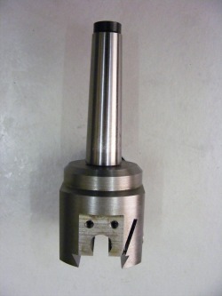
The MT2 taper was machined from 3/4" round bar and the end threaded 12 mm for a length of 12 mm. The narrow end of the taper was drilled out and tapped M10 for the draw bar.The body was made from a piece of 50 mm round bar. This was faced and drilled and tapped 12 mm to accept the taper. The other end of the bar was faced and the block was mounted in the milling vice on its curved face. A flat was milled on the curved face as shown in the photo (facing the camera) and then an 8 mm hole drilled through the bar. This hole made the channel for the feed screw. The bar was rotated 90 degrees and a flat milled on the side. It was again rotated, 180 degrees this time, and another flat milled. The bar was then turned so that it was lying on its end face and gripped by the flats. The section between the dovetails was milled away. The dovetails were milled. The feed screw channel was opened out using a 7 mm milling cutter. Two holes were drilled, tapped and counterbored, to accept M4 screws, in the right hand side. These screws can be clearly seen in the header photo. The slit on the right hand side of this photo was cut using a 1.5 mm slitting saw. The purpose of this slit is to allow a little movement so that when the M4 screws are tightened then the dovetail will clamp onto the mating dovetail of the toolholder block. After cutting the slit the M4 threaded holes were opened out to 4.5 mm to the depth of the slit. Once these operations have been done the taper can be screwed into the block. The internal thread in the block and the male thread on the taper were smeared in epoxy resin prior to assembly.
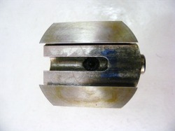
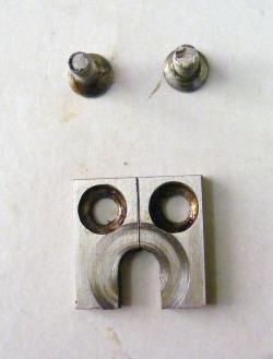
This shows the underside of the block with the feed screw channel in the middle and the two dovetails either side. The protruding piece on the right hand side is a piece of 8 mm round bar that is a force fit into the 8 mm hole forming the feed screw channel. It was drilled out 3 mm to support the end of the feedscrew.
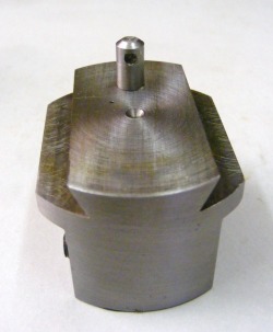
The lower tool holder part of the boring head was machined from a piece of 50 mm round steel. The dovetails were machined to closely match the mating dovetails in the upper part of the boring head. The protruding pin is the leadscrew nut. This is made from a piece of 6 mm round bar that is a good sliding fit into a hole bored in the tool holder. It is not fixed in any way. The hole in the nut is tapped M3. One of the tool clamping screws can be seen on the lower left hand side. This piece is relatively easy to make compared with the upper part.
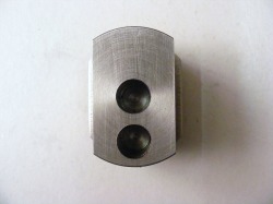
This photo shows the bottom of the tool holder block. The two holes are bored to 12 mm to accept the boring bars. These holes are not drilled until the piece is mated and clamped with the upper part of the boring head.
Once both halves of the boring head had been made, they were slid together, lined up and clamped together using the clamping screws. The whole assembly was mounted in the headstock taper using a MT3 - MT2 adaptor. The outside was skimmed along the entire length to clean it up and the diameter reduced at the top. An 11mm hole was then drilled in the base to a depth of 20 mm and this was opened out to 12 mm using a boring bar. Once this hole was made the clamps were loosened and the tool holder block displaced 16 mm with respect to the upper part and then re-clamped. A second hole was drilled and bored out to 12 mm. Having two positions for the boring bars increased the range of hole sizes that can be bored using the head. Boring the holes on the lathe in this way ensures that the axes of both holes are coplaner with the axis of rotation of the taper.
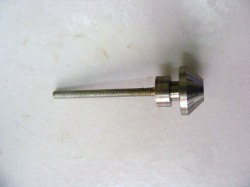
The feed screw is a piece of M3 studding (3 mm OD, 0.5 mm pitch). This was screwed, and fixed with Loctite, into the graduated knob. This has 50 division enabling setting to 0.025 mm. The head of an M4 socket head screw was pressed into the centre of the knob to permit adjustment. The 3 mm groove immediately behind the knob is for the leadscrew retainer plate.
Most constructors of boring heads use a much more substantial feed screw. However, the feed screw only has to move the two halves of the boring bar with respect to each other and the load to do this is trivial. During cutting there is no load on the feed screw because the top and bottom parts of the boring head are clamped together. The benefits of the finer feedscrew are that the feed per rotation is smaller and therefore potentially more accurate and the feed screw channel can be quite small.
Most constructors of boring heads use a much more substantial feed screw. However, the feed screw only has to move the two halves of the boring bar with respect to each other and the load to do this is trivial. During cutting there is no load on the feed screw because the top and bottom parts of the boring head are clamped together. The benefits of the finer feedscrew are that the feed per rotation is smaller and therefore potentially more accurate and the feed screw channel can be quite small.
The retainer plate is made from a piece of 3 x 20 x 20 mm steel. This screws onto the milled flat surface at the end of the feed screw channel. The scribed vertical line on the retainer plate is the index line for the graduations on the knob.
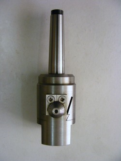
This final photograph shows the boring head completed with the retainer plate screwed into position.
