Leadscrew handwheel
Whilst the carriage handwheel provides a quick and easy way to move the carriage large distances, it is not precise. A handle attached directly to the leadscrew gives much more precise control of the carriage position. It is almost essential if the Sieg milling attachment is to be used with the lathe. There have been a large number of leadscrew handwheels descibed on the web for the minilathe. Usually these are permanently attached to the leadscrew and as a consequence the handwheel turns even when the leadscrew is in autodrive. Being a rather untidy worker, who often leaves bits and pieces at the end of the lathe bed, I was a little concerned that objects could become jammed under or knocked over by the leadscrew handle. The leadscrew can rotate quite fast during screw cutting operations.
To overcome this problem I sought to design a handwheel that could be disengaged from the leadscrew when not in use. In order to fix a leadscrew handle to the lathe it is necessary to join the handle to the leadscrew. To do this most designs require that the leadscrew is bored out at the end and a spigot connected to the leadscrew is then loctited or epoxied into the end of the shaft. In this design the leadscrew is also drilled out but a miniature expanding mandrel, connected to the handwheel, is used to make the connection. The expansion of the mandrel is actuated by a separate knob that then allows the handwheel to be connected or disconnected at will.
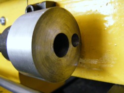
The lead screw was first wrapped in 80 gsm paper before chucking in the lathe. It was drilled out 6 mm diameter for a length of 20 mm.
To overcome this problem I sought to design a handwheel that could be disengaged from the leadscrew when not in use. In order to fix a leadscrew handle to the lathe it is necessary to join the handle to the leadscrew. To do this most designs require that the leadscrew is bored out at the end and a spigot connected to the leadscrew is then loctited or epoxied into the end of the shaft. In this design the leadscrew is also drilled out but a miniature expanding mandrel, connected to the handwheel, is used to make the connection. The expansion of the mandrel is actuated by a separate knob that then allows the handwheel to be connected or disconnected at will.
The lead screw was first wrapped in 80 gsm paper before chucking in the lathe. It was drilled out 6 mm diameter for a length of 20 mm.
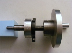
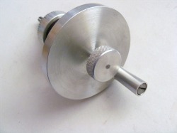
This photo shows the complete leadscrew handwheel assembly. From left to right can be seen the small expanding mandrel (6 mm diameter), the leadscrew hand wheel shaft (12 mm diameter) carrying the graduated collar, a support bracket (black) which bolts on to the lathe bed, another section of shaft (8 mm diameter) and the handwheel itself. There is an O ring in a groove under the graduated collar that provides a friction drive to the collar. Not shown in the photo is an M4 threaded shaft that passes through the handwheel and shaft into the expanding mandrel. The shaft is drilled out 5 mm diameter except at the expanding mandrel end.
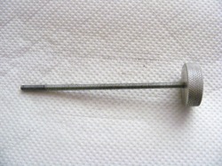
This is the M4 threaded shaft that passes through the assembly shown above. The purpose of this screw is to expand the mandrel so that it grips the end of the leadscrew. This was made from a length of M4 studding. The knurled aluminium knob was attached to the shaft with epoxy resin.
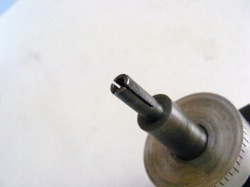
This is the expanding mandrel at the end of the shaft. It is made separately from the shaft by taking a 25 mm length of M8 studding and boring it out to 3.3 mm for a length of 20 mm. This is then threaded with an M4 taper tap until the tip just reaches the end. This forms a tapered thread inside the stud. The stud is then screwed into a M8 tapped hole in the end of the shaft so that approximately 15 mm protrudes from the end of the shaft. Epoxy resin is used on the thread to make a good bond to the shaft. The shaft is then mounted in the lathe chuck and the outside diameter of the protruding stud is reduced to 6 mm removing the outside threads in the process. The end of the mandrel is then slit into four segments as shown. When the M4 threaded shaft, shown in the previous photo, is passed through the handwheel shaft into the threaded end of the expanding mandrel and screwed up, using the knurled knob, then the 4 segments are expanded outward as the screw is tightened.
This shows the M4 threaded shaft inserted through the handwheel, through the bore of the shaft and screwed into the expanding mandrel. The hole in the handwheel is drilled out 4 mm.
Here is shown the aluminium collar that is attached to the right hand leadscrew pillow block. This collar supports the the 12 mm shaft and also carries an index mark against which the graduated collar can be read.
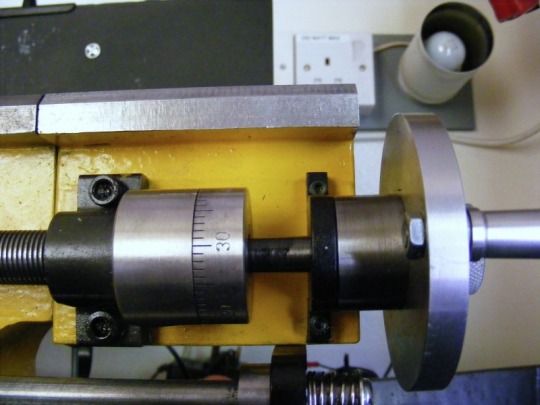
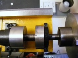
The header photo shows the completed assembly on the lathe. In this photo the hand wheel has been pushed to the left so that the expanding mandrel is engaged inside the 6 mm bored out section of the leadscrew. The threaded shaft has been tightened to expand the mandrel which is now locked to the leadscrew
This photo shows the leadscrew disengaged from the handwheel. The threaded shaft has been unscrewed a little causing the mandrel to contract. The shaft is then pulled out to the right removing the mandrel from the bored out section of the leadscrew. The leadscrew is now disconnected from the handwheel and does not turn if the leadscrew rotates.
