Mill fixed column modification.
I have had my Super X1L mill for many years and it has served me well in that time. I have done a number of improvements to it over the years adding stops, belt drive and power feed. It has only a 150 water motor so deep one, pass cuts are not easy and normally multiple passes are needed to remove significant amounts of metal. For some time I considered buying a more powerful mill such as the Sieg X2 model but then I realised that most of my tooling is MT2 taper and this would not be compatible with the bigger mill. In the end I decided to keep the Super X1L and to spend some money on some improvements.
The mill was fixed in a small tray barely larger than the base of the mill. The table overhung the tray so any cutting oil would drip from the table onto the bench. The tray also fouled the front handwheel of the milling table. The base casting on my mill was very rough in places, making it difficult to keep clean, and I wanted to smooth this down in places and give it a good coat of paint.
The mill had a tilting column. It took me so long to tram the mill when I first had it that I was reluctant to use the tilting facility because of the need to re-tram the mill afterwards. I believe, from discussions on various fora, that most people never use the tilting facility because it is simpler to simply tilt the work on the table. I also wanted to increase the Z-axis range of the mill. The height of the column can be increase by adding riser blocks under the column. However, will the tilting column any increase is height also reduces how closely the column can approach the milling table. The answer to this problem was to change the column to the fixed column option that is used on some versions of the X1 mill. My Super X1L mill was supplied originally by ArcEuroTrade and I contacted them to see if they could get me a fixed column. They responded quickly saying they could get one on special order and they have since added it to their spares list.
The project plan was as follows:
1. Make a new, longer Z axis leadscrew. Thiis has to be done first because the mill was needed to cut a key way.
2. Strip down the mill.
3. Clean up the base and repaint.
4. Mount the base on riser blocks in a new tray.
5. Make the new components for mounting the fixed column.
6. Reassemble the mill.
7 Re-tram the mill
|
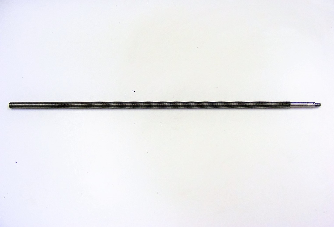
The new, longer z-axis leadscrew was made from a length of M10 left hand threaded studding supplied by GWR Fasteners Ltd.
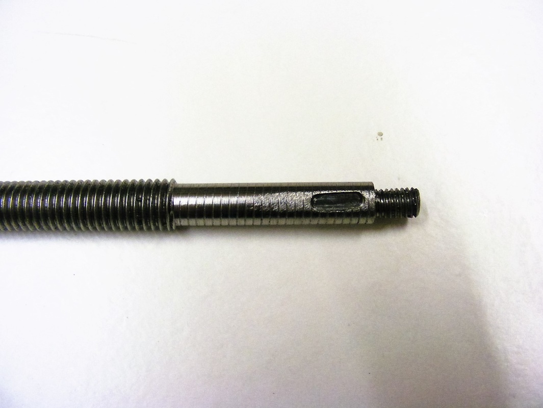
In the lathe this was gripped in the chuck and turned down to 8 mm for 46 mm. The end of this reduced section was turned down to 6 mm for 9 mm and then threaded M6. |
|
The leadscrew was gripped in a small vice on the mill and a 3 mm keyway cut as shown here.
|
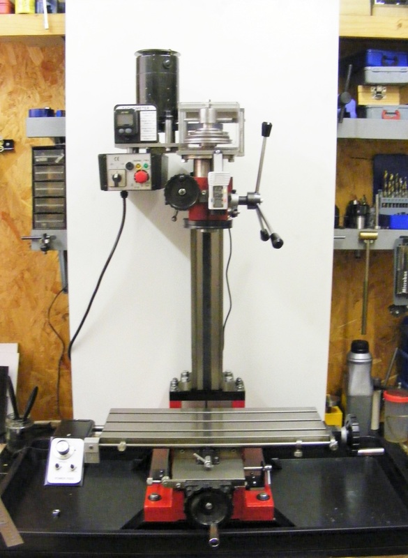
The new tray, shown in the header photo was purchased on ebay and is described as "Garland Maxi Garden Tray Black". It was made of plastic and was 790 x 400 x 50 mm.
|
To raise the base of the mill above the level of the tray two riser blocks were cut from 50 x 50 x 3 box section steel
|
|
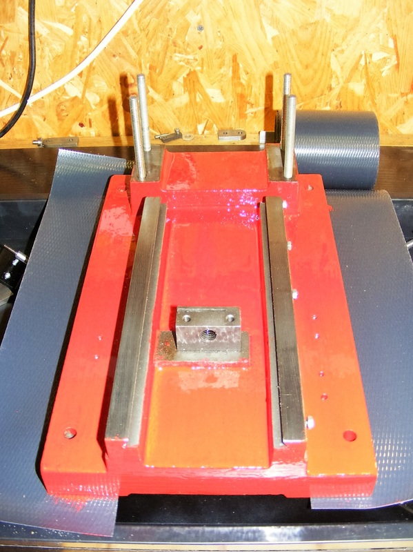
The rough places on the mill base csting were carefully cleaned up with a Dremel type tool and then given a coat of paint.
The paint used was purchased at my local Wilko store. It was a good match to the original colour of the mill. The paint is described as Wilko Outdoor Gloss colour Signal Red |
|
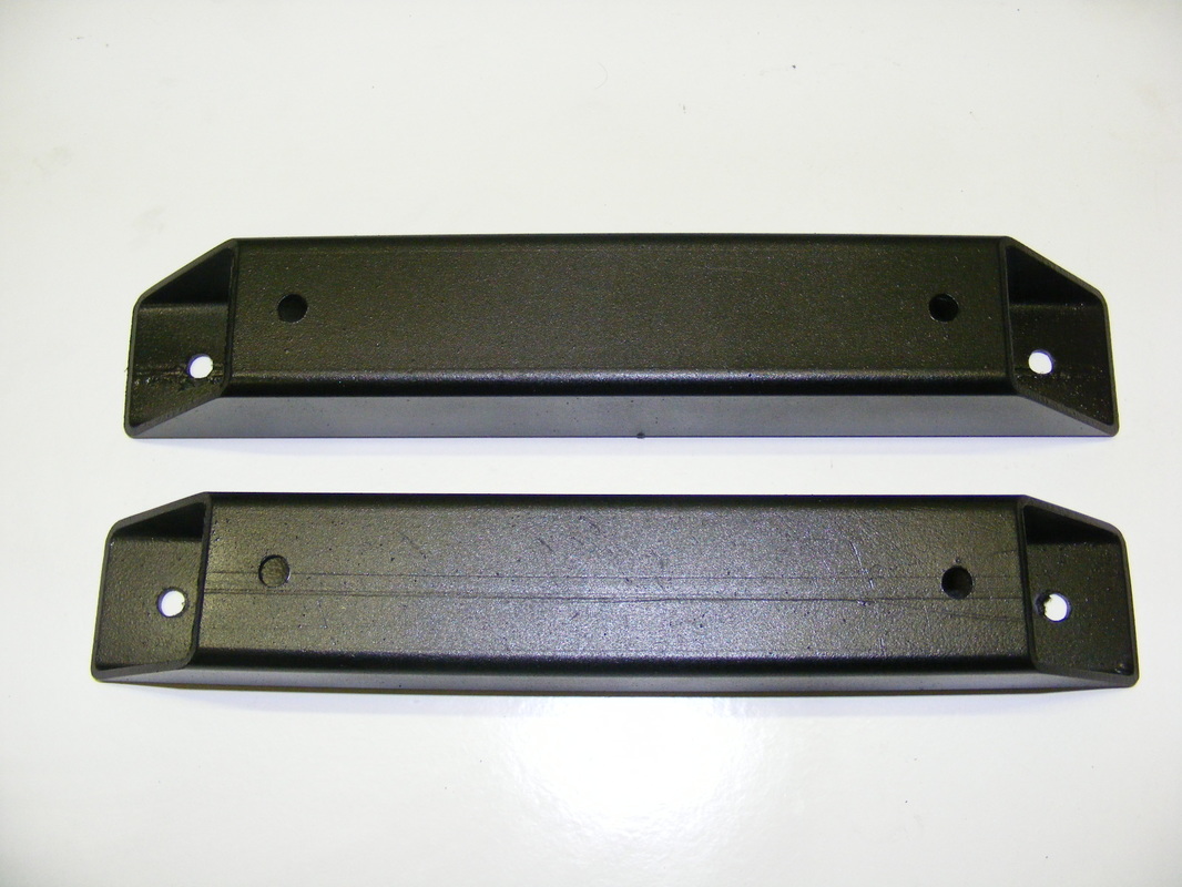
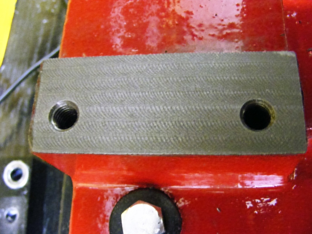
The hole spacing on the fixed column are different from the hole spacings on the tilting column so it was necessary to make an adaptor plate. This was was made from 20 x 70 bright mild steel bar.
Also shown in the photo are the two column riser blocks. These were made from 25 x 50 bright mild steel bar |
|
The riser block were painted red to match the base and the adaptor plate was sprayed black to match the column base.
|
|
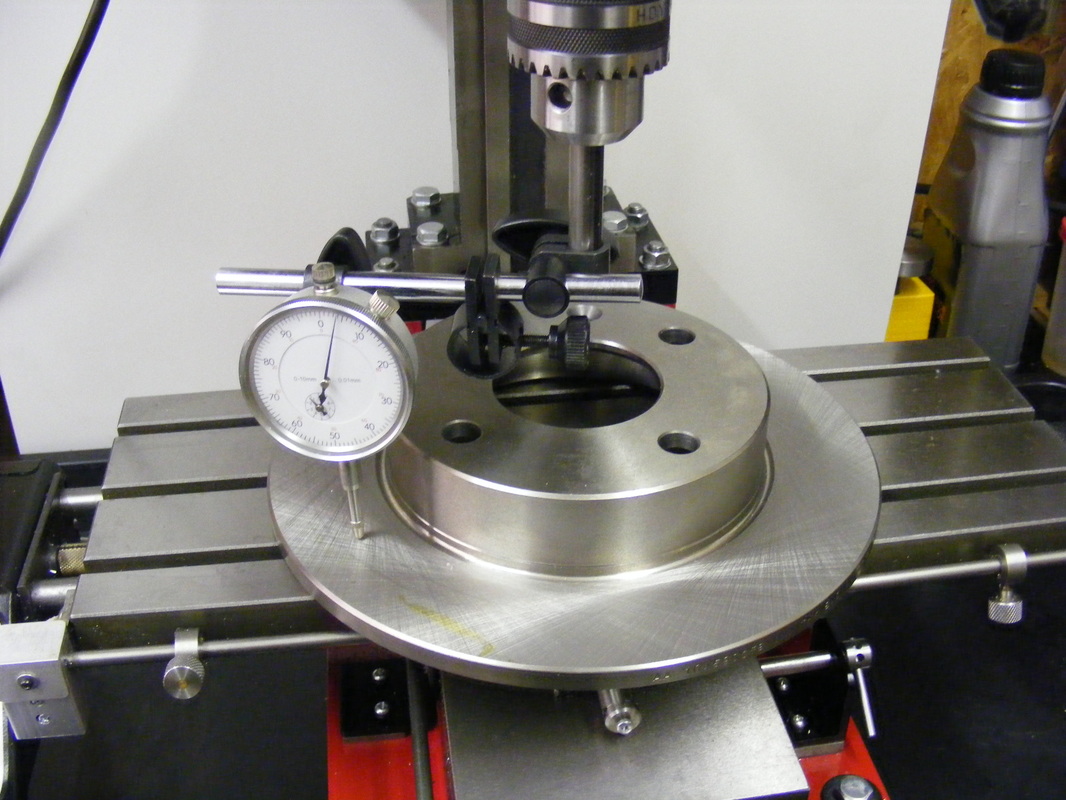
The mill was reassembled and re-trammed. A new Ford Fiesta brake disk was used as a reference surface for tramming as shown here.
It was very difficult to re-tram the mill. On close inspection of the base mounting pads beneath the riser blocks the surface was found to be very uneven. |

|
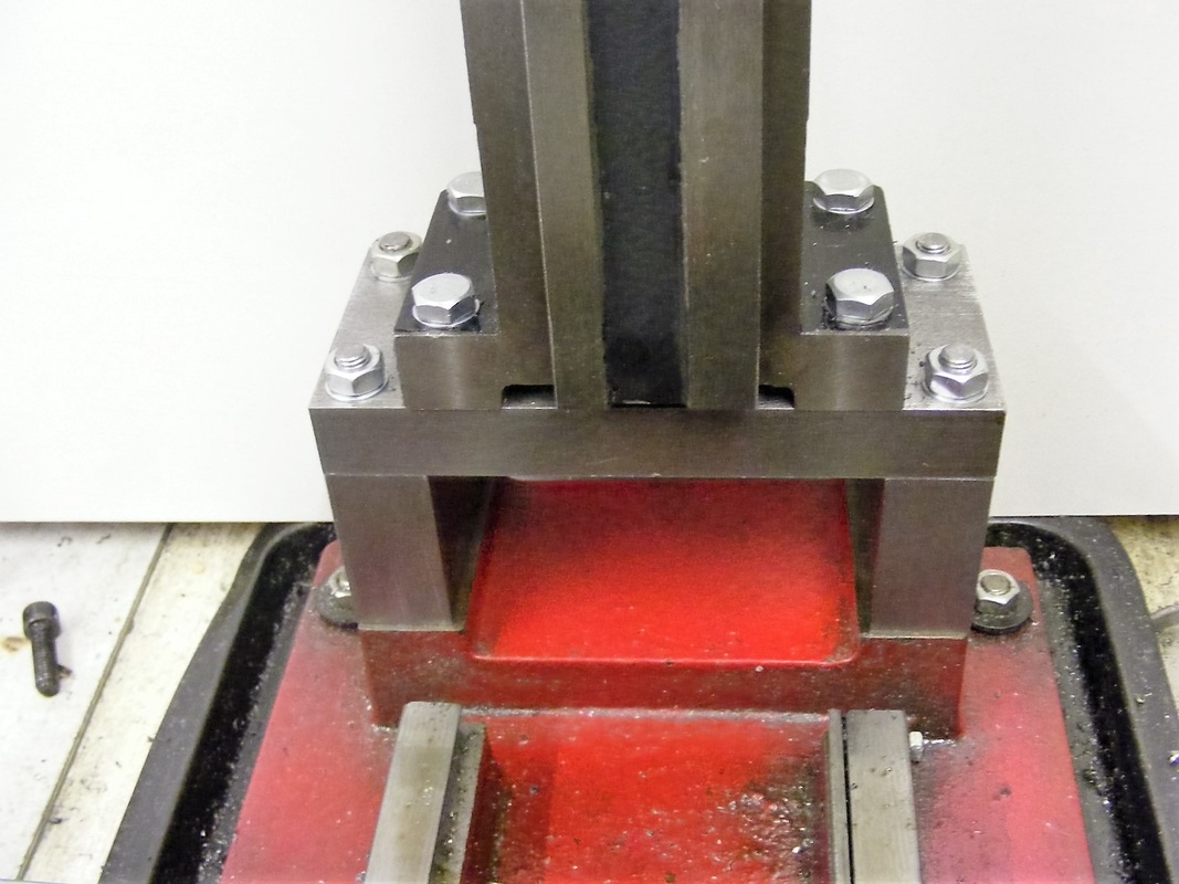
This shows the base mounting pad.
|
|
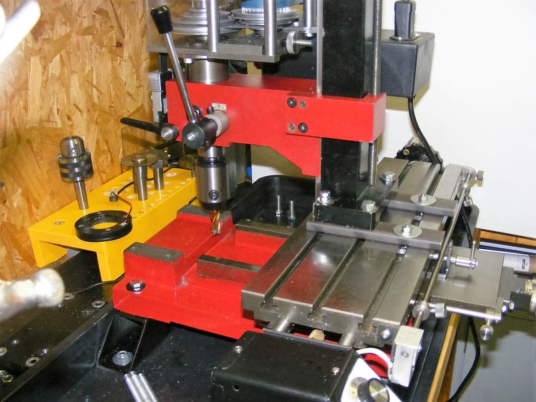
To true up the surface of the pads the mill column was mounted backwards on the mill table as shown here. With this arrangement it was possible to mill the top surface of the mounting pads using the table X and Y handles to move the cutter over the pads. This levelled the pads and made them exactly parallel to the mill table.
|
|
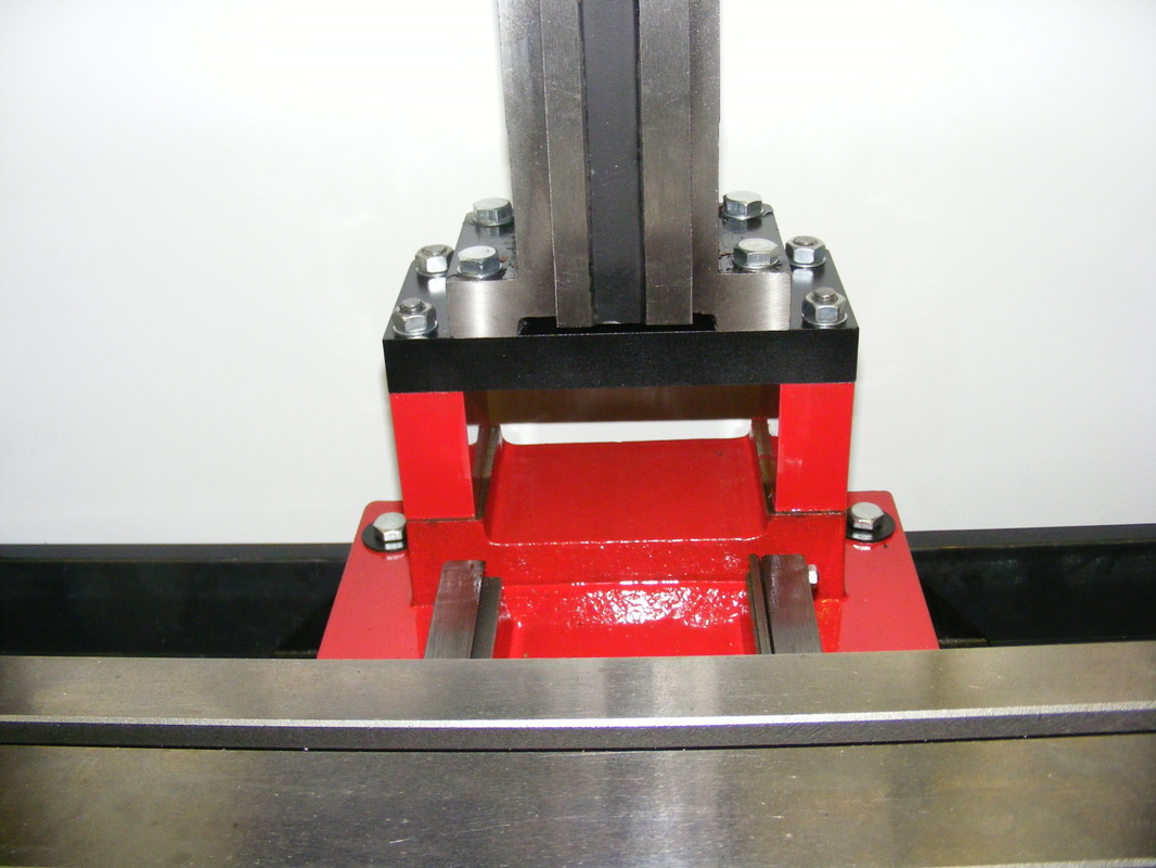
This photo shows the pads after milling the surface.
The mill was reassembled and re-trammed. Tramming was very easy and only a small piece of aluminium cooking foil was needed as shimming to get a perfect tram. |
The project has resulted in some significant benefits. The main benefit is that the z-axis range has increased. The standard Super X1L mill has a quoted z-axis range from 45-265 mm measured from the spindle to the milling table. After the modifications it is 17-350 mm.
The two riser blocks eliminate an impossible to clean gap under the column that was present with the tilting column. The smooth re-paint job has also eliminated some dirt traps on the machine base.
The large tray catches all the drips that run off the table and the bench stays clean
The two riser blocks eliminate an impossible to clean gap under the column that was present with the tilting column. The smooth re-paint job has also eliminated some dirt traps on the machine base.
The large tray catches all the drips that run off the table and the bench stays clean
