Soft Jaws
Soft jaws for the lathe chuck are very useful particularly for holding circular object that might be crushed by normal jaws. The jaws can be machined to grip the object around most of its circumference. Another use is to hold thin workpieces. Here a recess can be machine into the jaws to accommodate a thin object. Harold Hall has many more examples of there use on his website.
However, soft jaws are not readily available for most of the cheaper asian lathe chucks. Some of the advantages of soft jaws can be had by making loose chuck jaws these are quite limited. The present project was initiated to try to make soft jaws that could be attached to the existing chuck jaws.
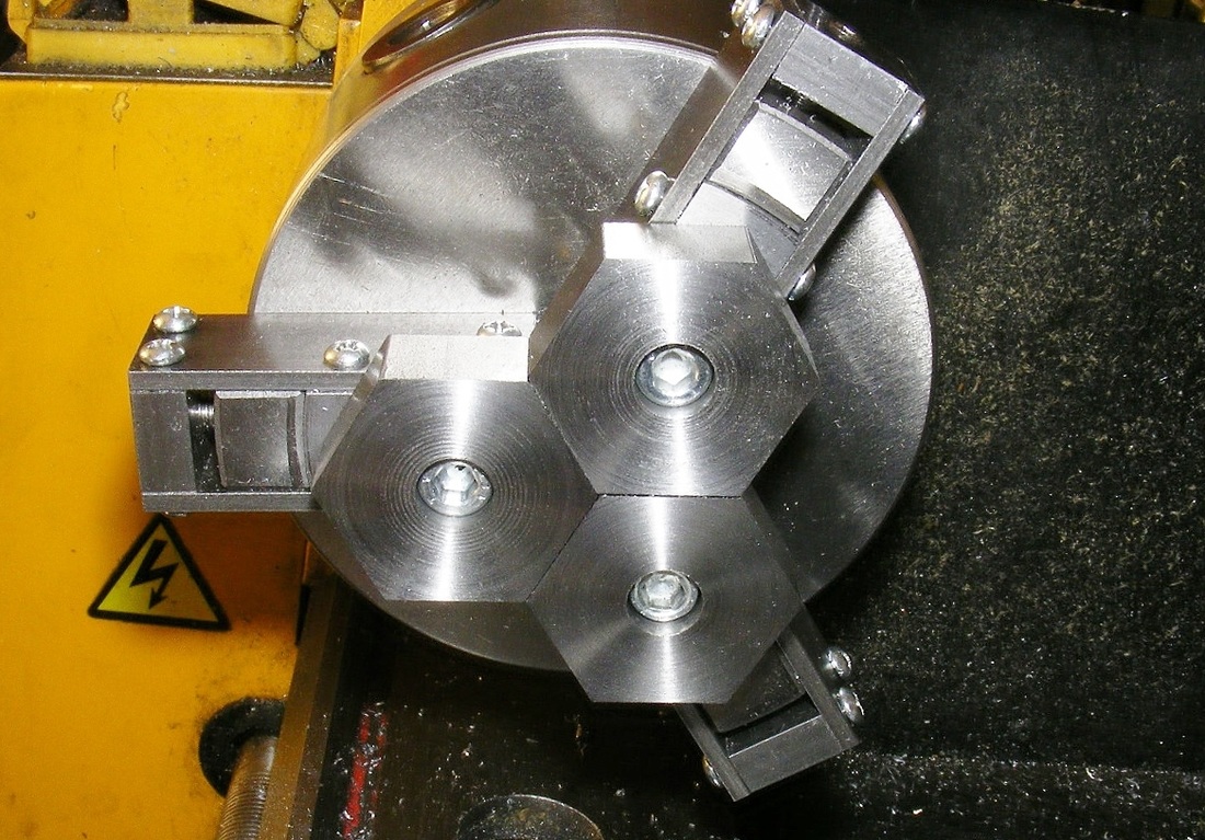
The header photo shows the soft jaws. These consist of three fabricated clamps that fit onto the normal outside jaws of a three jaw chuck. The hexagonal soft jaws are separate and they are bolted onto the clamps.
The real challenge in designing the soft jaws arises because the soft jaws above the true chuck jaws and hence as the chuck is tightened it tend to force the clamps off of the jaws. This problem was overcome by making the soft jaw clamps lock onto the true chuck jaws.
However, soft jaws are not readily available for most of the cheaper asian lathe chucks. Some of the advantages of soft jaws can be had by making loose chuck jaws these are quite limited. The present project was initiated to try to make soft jaws that could be attached to the existing chuck jaws.
The header photo shows the soft jaws. These consist of three fabricated clamps that fit onto the normal outside jaws of a three jaw chuck. The hexagonal soft jaws are separate and they are bolted onto the clamps.
The real challenge in designing the soft jaws arises because the soft jaws above the true chuck jaws and hence as the chuck is tightened it tend to force the clamps off of the jaws. This problem was overcome by making the soft jaw clamps lock onto the true chuck jaws.
|
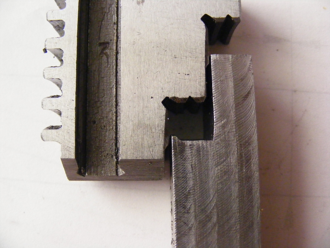
This photo illustrate how the clamps lock onto the chuck jaws. Each clamping piece is shaped to match the curvature of the outside jaw and it is also shaped with a small projection that fits into the recess at the bottom of the chuck jaw step.
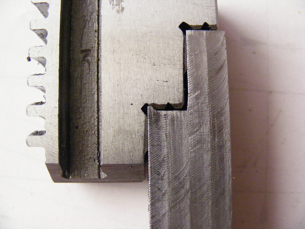
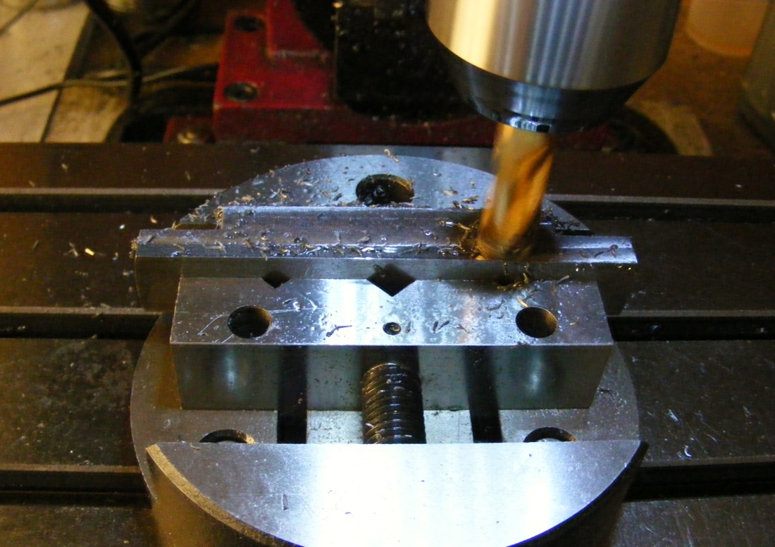
This photo show the clamp profile pushed onto the chuck jaw. Here the clamp profiles are being turned. For my chuck the bar was 16 mm square. The bar was 104 mm long and the centre line was marked and the centre of the face was found and centre punched. Two further punch marks were made at 40 mm either side of the centre point. These were drill and tapped M6. The bar was then attached to a piece of 6 x 19 mm bar using two M6 screws into the threaded holes. This assembly was mounted in the four jaw chuck as shown here. The centre point of the bar was then brought on axis using a DTI. |
The outer end of the bar was turned down to a diameter of 102 mm. The bar was turned down to a diameter of 71.5 mm for a distance of 7 mm to form a step. Using a specially profiled lathe tool the step was then turned down to 70 mm except at the outer edge which was cut to form a 45 degree wedge as shown in the photos above.
|
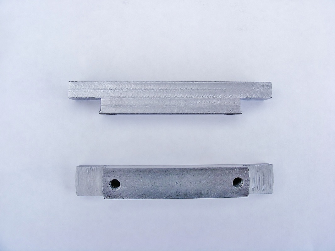
The chuck jaws were 15 mm wide.
The bar was removed from the chuck and its width was reduced to slightly greater than the width of the chuck jaws on the mill. The finished bar after machining |
The two ends of the bar were then cut off 32 mm from each end to provide pieces for two clamps.
Since three clamps are required it is necessary to profile two bars and end up with four clamp pieces, one of which is unused.
Since three clamps are required it is necessary to profile two bars and end up with four clamp pieces, one of which is unused.
|
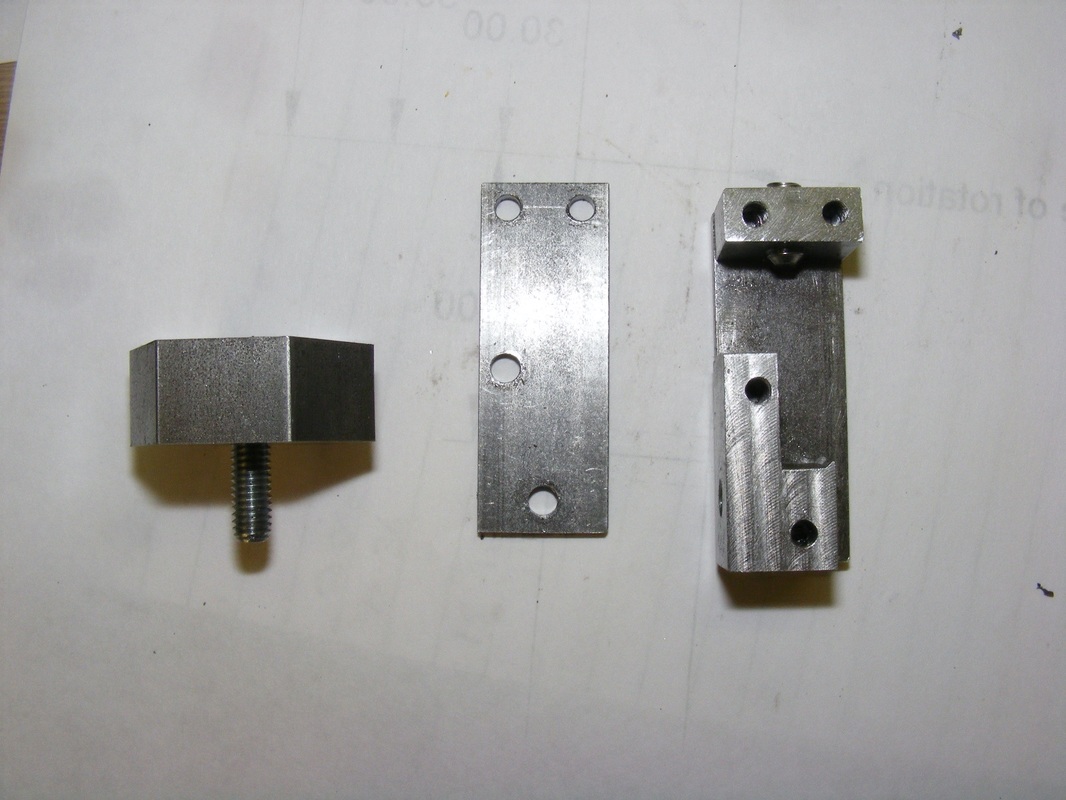
This photo show the assembly of the various parts. The profiled pieces are attached two side plates made from 3 x 20 steel using M4 screws.
The end plate is cut from 8 x 20 mm steel and it is also attached with M4 screws. It is also drilled and tapped through centrally for an M6 grub screw. The component on the left is the soft jaw. This is 13 mm thick and it was cut from 32 mm hex bar. Both ends are faced. It is drilled through 6 mm and counterbored 10 mm to a depth of 9 mm |
|
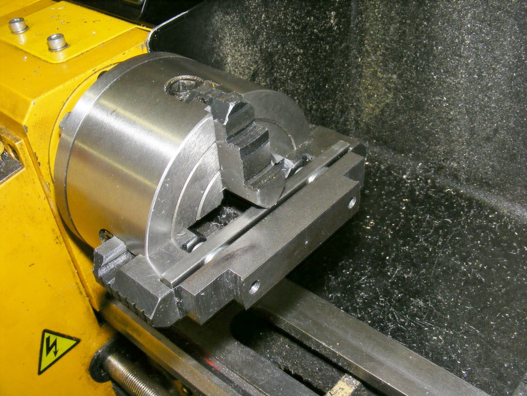
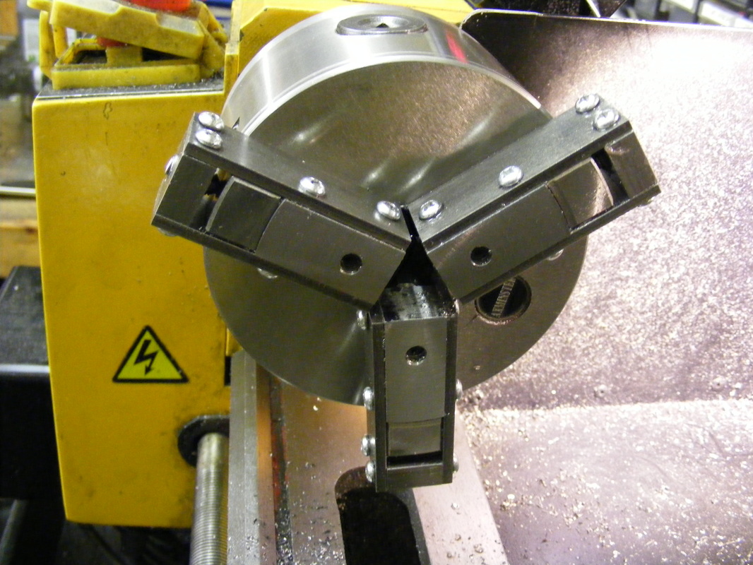
Once the clamps were assembled they were fitted onto the chuck jaws, as shown here.
The front face of the profiled pieces were then machined flat and level. |
The final operation was to attach the hexagonal jaw pieces, as shown in the header photo.
