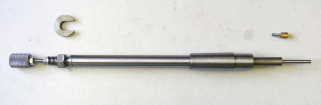
Chuck backstop and disc alignment tool
There was an interesting posting recently on the madmodder website (http://madmodder.net/index.php?topic=3485.0) where someone used a magnetic base for a dti, chucked in the tailstock, to hold a disc and then set it up in the lathe chuck so that the flat face of the disc was aligned at right angles to the axis of rotation.
Whilst this technique is very clever it struck me that it would be even better if the the magnetic base was much smaller and inside the chuck. Many times I have had an odd piece of round bar perhaps only 10 mm thick left from a job and have wanted to turn this into a disc faced, and parallel, on both sides for another job. Setting this up in a chuck is difficult to do accurately. If the disc could be held on a magnetic platter inside the chuck and then gripped by the chuck then the outside face of the disc can be machined. Once this surface is flat then the disc can be turned over and the procedure repeated. The result would be a disc faced both sides with both faces parallel.
The tool described here is similar to a chuck back stop but it incorporates a magnetic tip allowing flat discs to be set up at right angles to the axis of rotation. It can also be used as a chuck back stop.
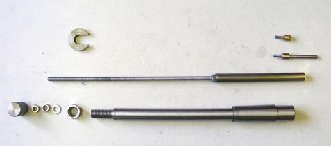
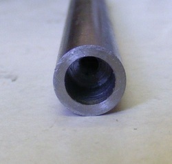
The unit comprises several components. At the bottom of the photo is the main tube. This has an MT3 taper at one end that fits into the headstock. The other end is threaded M12. The tube is clamped into the headstock by the large nut and C washer shown on the left.
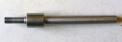
Above the main tube is the sliding part of the assembly. This is a piece of 12 mm rod with a length of M6 studding screwed into the left hand end.
At the upper right hand side of the photo are two alternative tips that can be screwed into the right hand end of the sliding component. One is a small magnet, for disc alignment and the other is a thin tip for use as a backstop.
At the lower left of the photo are a washer, two M6 nuts and a knurled knob. The washer and one nut can be used to lock the sliding part in the tube. The knurled knob screws onto the end of the sliding part and is locked on by the other nut.
The whole assembled unit, with the exception of the C washer, will slide through the headstock.
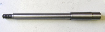
The main tube comprises an MT3 taper with an extended nose, a piece of 16 mm tube with 1 mm wall thickness, and a threaded end piece on the left. These are all made separately and then joined together with epoxy resin.
The taper is made first. A full taper is not required since it is only used to accurately locate the sliding component. An 80 mm length of 25 mm round bar is chucked in the lathe and the far end supported in a fixed steady. This is centre drilled and then drilled out to 4 mm for a length of about 45 mm. The hole is then opened out to 13 mm for a depth of 15 mm. The end is then bored out to 16 mm to accept the 16 mm tube. Finally the the inner edge of the hole is chamfered at 30 degrees. The fixed steady is removed and the end of the bar the supported with a live centre in the tailstock chuck. The taper can then be cut using either an angled top slide ( see extended top slide) or using a taper turning attachment.
The threaded left hand piece is made next. This is made from a piece of 16 mm round bar 48 mm long. The end is turned down for a length of 15 mm to be a snug fit in the 16 mm tube. The other end is turned down for a length of 30 mm to a diameter of 12 mm and then threaded M12. A 5 mm hole is drilled through the component and then counterbored 6 mm for a depth of 38 mm. The 5 mm hole is then tapped M6.
A piece of 16 mm tube is then cut to 165 mm length.
The three components can then be assembled. First they are thoroughly cleaned with white spirit and dryed off. Epoxy resin is applied to inside of the recess in the taper and to the outside of one end of the tube and the two components pushed together. The stub of the threaded piece and the inside of the tube are then coated on epoxy resin and then pushed together. To ensure good alignment of the parts, the assembly is then mounted in the lathe with the taper held in the lathe chuck and the threaded component held in the tailstock chuck. Apply pressure with the tailstock and wipe off any excess adhesive. Leave in the lathe overnight for the adhesive to set.
Once the adhesive has set remove the tail stock chuck and clean up the assemby by polishing it with 320 grade emery cloth and oil. Remove the assembly from the chuck. Remove the chuck from the lathe and insert the taper in the headstock spindle. Using an M12 washer and nut clamp it in place at the other end of the spindle. Face off the end of the taper, centre drill and then drill through with a 4mm drill. This should meet up with the hole partially drilled through the taper at an earlier stage. Enlarge the hole in stages to 11.8 mm and ream out to 12 mm. Turn the protruding part of the taper back to 20 mm diameter so that it will fit into the back of the lathe chuck. (Note I have a 100 mm chuck on my lathe. If you have an 80 mm chuck you will have to turn the protruding part to a smaller diameter to fit the smaller chuck.) Chamfer the edge of the nose and use a countersink to bevel the inside of the hole.
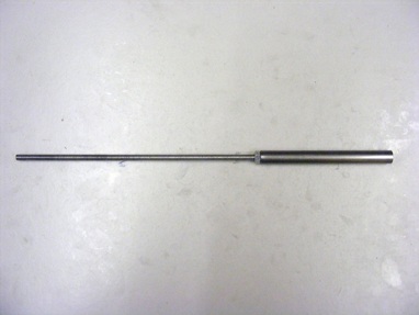
The sliding component consists of a 120 mm length of precision 12 mm round bar. This is drilled and theaded M6 at one end and a 220 mm length of M6 studding screwed in and locked in place with an M6 nut.
This sliding part goes inside the main tube and screws into the threaded hole at the far end.
This sliding part goes inside the main tube and screws into the threaded hole at the far end.
The other end of the sliding bar is drilled out 3.3 mm for a length of 35 mm and then counterbored to 8 mm for a length of 12 mm. The 3.3mm drilled section is tapped M4.
This socket is to accept the tips for the tool. These screw into the M4 hole.
This socket is to accept the tips for the tool. These screw into the M4 hole.
This is the tip for use when the tool is used as a chuck back stop. It is turned from 8mm round bar stock. The front end is turned down to 5 mm for a length of 40 mm, The centre section is 8 mm diameter and the other end in turned down to 4 mm and threaded M4. Other sizes could be made to suit different purposes.
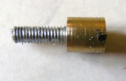
This is the magnetic tip. It consists of a piece of 8 mm brass bar 9 mm long. It is drilled through with a 4 mm drill and then counterbored for a length of 6 mm with a 6 mm drill.
The head of an M4 countersink screw is turned down to fit in the 6 mm counterbore. Slots are cut on a diameter about 2 mm deep. One of the slots is visible in this photo.
The inside of the counterbore is coated with epoxy resin and the screw inserted and then a 6mm diameter x 3 mm thick rare earth magnet inserted. This assembly is then left for the adhesive to set.
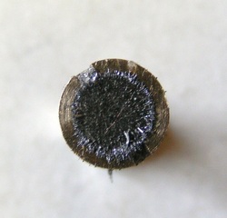
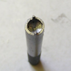
This is an end on view of the magnetic tip. Once the adhesive has set then the brass is turned away to leave the brass level with the surface of the magnet.
Note the two slots either side of the magnet. This slots are used to screw the tip into the sliding component using a special tool to be described later.
The tip screws into the end of the sliding component. The surface of the magnet should be adjusted just below the level of the end of the sliding component so that the accurately faced edge of the steel acts as a reference surface against which a disc is held. If the end of the sliding component gets worn or damaged then the magnet can be screwed in a little way and the tip of the sliding component refaced.
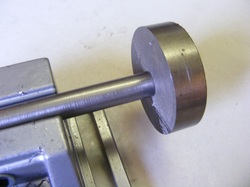
The strength of the magnetic tip is impressive. In this photo it is supporting a 2" diameter x 18mm thick slice of steel bar.
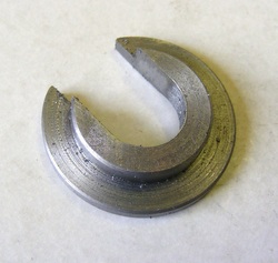
The C washer is machined from 28 mm round steel bar. It is faced and then a 3 mm long shoulder is turned 20 mm diameter to fit the spindle bore. The bar is then parted off at 5 mm from the end. The piece is then reversed in the chuck and faced.
The slot is cut using a hacksaw and then finished with a file so that is fits over the threaded end of the main tube.
The slot is cut using a hacksaw and then finished with a file so that is fits over the threaded end of the main tube.
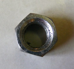
A standard 12 mm nut will not fit through the bore of the spindle so a special nut was made by taking a standard nut and milling 1 mm from each face. The edges of the nut are then chamfered.
The completed tool is shown in the header photo. The knurled knob is 18 mm diameter and it is locked in place with a 6 mm nut.
The special tool for screwing the magnetic tip in place is made from a length of 8 mm bar stock. This was drilled out 6 mm and the end filed to leave two small prongs that fit in the grooves of the magnetic tip.
This gadget works remarkably well. When used as a chuck stop it is similar to other units that have been designed. However, the magnetic tip is very useful for setting up discs accurately in the chuck for machining. It will also handle square, or other shaped flat parts, that can be chucked in a four jaw chuck.
