Large fixed steady.
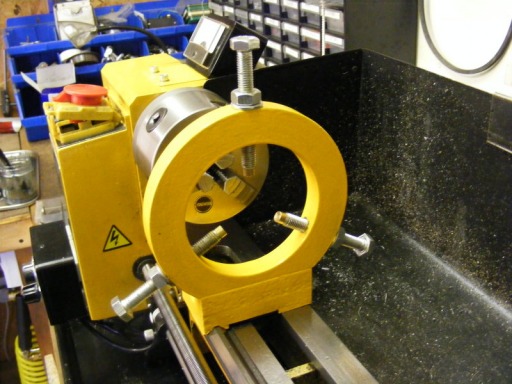
The standard Sieg fixed steady is a little small and this limits the diameter that can be held to about 30 mm. This project was started to try to overcome this limitation. For me it was a significant event because it was my introduction to aluminium casting, see the foundry section.
The steady was made in two parts: the ring and the base. The ring pattern was cut out of polystyrene foam using a hot wire cutter and the base pattern was also modelled from polystyrene blocks cut with the hot wire cutter. The ring is 18 mm thick, the inner diameter 95 mm and the outer diameter 145 mm. A polystyrene sprue was glued to the ring and it was buried in loose, dry, fine builders sand. Molten aluminium was poured into the sprue at a steady rate until the it overflowed from the sprue. The base was cast is a similar way. This process is called lost foam casting and it is very convenient for one off castings.
After casting the sprue is cut off and the ring surfaces skimmed on the lathe. Whilst in the lathe the position of the finger bolts was marked onto the ring. M10 holes were drilled and tapped at these positions for the finger screws.
A flat was milled onto the ring to form a mating surface with the base.
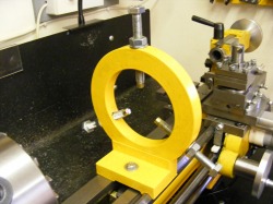
This photo shows the other side of the steady with the mounting bolt.
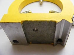
Here is the underside of the base. The bottom surfaces were milled flat. To form the vee groove a slot was first cut and then a 90 degree HSS countersink used as a milling cutter. At the bottom of the photo can be seen the holes for the socket head screws that attached the ring to the base.
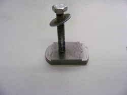
This shows the clamping bolt. It is designed so that it will slip between the gap in the ways and then twisted to lock down between the ways. This is much easier to use than the standard Sieg flat, rectangular clamping plate that requires much tedious fiddling to get into place.
The fingers are standard 10 mm hex head screws. The tip of each screw is drilled out and a stepped brass plug inserted to act as a bearing surface on the work piece.
