Mill belt drive conversion.
The Sieg X1L is a fairly robust little machine and I have used it for many years with few problems. Being a small mill means that it has its limitations and large cuts are not possible in one pass but they can be accomplished with multiple passes. A number of users have reported that they have broken the gears during arduous use. This has not happened to me and my main complaints are that the gear train is noisy (mainly the selector fork rattling) and that the range of speeds is insufficient. This conversion was carried out to cut the noise level and to increase the range of speeds to four. The top speeds chosen in each range were 500, 1000, 2000 and 4000 rpm. In order to easily fit the four speeds into a compact space it was necessary to use a narrow belt and the downside to this is that the belts have to be tensioned quite hard. This in turn meant that it was inadvisable to mount a multi pulley directly on the motor itself since the radial forces on the motor spindle would be very large. To overcome this I decided to use a timing belt from the motor to a layshaft carrying a four speed multi-pulley and then drive the mill spindle via another four speed multi-pulley. This keeps the radial forces on the motor spindle low and enables a high tension on the drive belt. The basic motor speed is 4000 rpm and the timing belt and pulley reduce the layshaft spindle speed to 2000rpm. The vee belt and pulley system then need ratios of 1:4, 1:2, 1:1 and 2:1 to achieve the desired speed ranges.
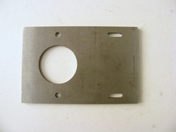
The new base plate was made from 1/4" x 6" flat, 100 mm wide. The large hole is for the spindle and the two smaller holes are for mounting to the quill flange. The slots are for mounting the motor assembly
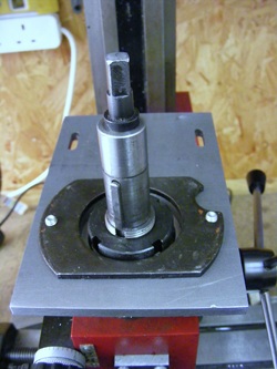
The base plate was mounted on the mill. The black plate is part of the old mill gear drive assembly that secured the gear box to the top of the quill.

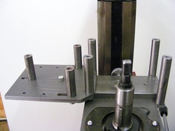
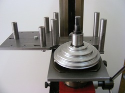
The supporting structure for the layshaft and motor. The three pillars on the left support the motor. They are fixed from below by M5 screws. The motor plate is slotted to allow belt adjustment. The ball bearing shown is a 608ZZ and is recessed into a piece of 10 x 50 mm flat which is bolted to the motor plate by the three hex head screws on the left. The remaining four pillars are fixed in position and support the top plate carrying the upper layshaft bearing. The pair of pillars on the right are attached to a pieces of 1/4" x 1/2" flat bolted to the underside. The screw and knurled adjuster are the belt tensioning mechanism. All the pillars are made from 1/2" round steel.
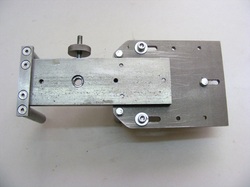
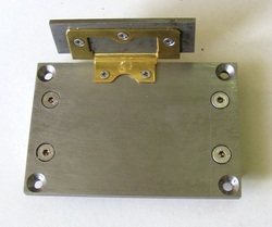
The underside of the assembly shown in the previous photo. Note the two holes either side of the bearing. These are tapped M5 and they are used to bolt this assembly to the base plate.
The assembly bolts onto the base plate from underneath by two M5 hex head screws. The slots in the base plate allow the whole assembly to be moved closer or nearer to the mill spindle axis to adjust the belt tension.
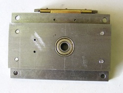
The top plate has a 608ZZ bearing recessed into a piece of 10 x 50 mm flat. This bearing supports the top of the layshaft. At the top can be seen the hinge for the Perspex guard. The two small holes to the left of the bearing are for the tachometer sensor.
This is the other side of the top plate complete with the guard hinge.
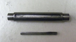
The layshaft is machined from 10 mm diameter steel and is turned down to 8mm at both ends to fit the bearings. It is grooved for the key shown below in the photo.
The layshaft assembly consists of the layshaft, key, the four step pulley and the timing belt pulley. Not shown are two small collars that fit at either end of the layshft to adjust the height of the pulleys on the layshaft. The 32 tooth timing belt pulley and the four step pulleys were both machined from rough aluminium castings made by the lost foam method.
The top of the layshaft timing belt pulley. Note the hole containing a small 8 x 5 mm neodymium magnet. This is to actuate the tachometer sensor
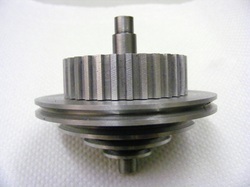
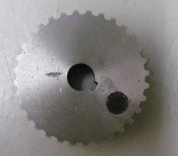
The spindle pulley was also made from an aluminium casting and machined to shape. It has a keyway and just slides onto the spindle and is held in place with a circlip.
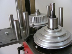
The layshaft inserted into the lower bearing. Note the loose collar on the top of the timing gear.
The top plate has been bolted onto the pillars and the guard attached to the hinge. The vee belt used was a 3M325 Polyflex belt made by Gates in the US. The timing belt is a 10 mm wide, T5 polyurethane belt with 61 teeth on a 5 mm pitch. Both belts were supplied by Beeline Engineering Products (www.beeline.co.uk) here in the UK.
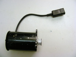
The motor has been disconnected from the controller and an IEC male plug wired to the cable. The 16 tooth timing belt pulley was a purchased component from Technobots (www.technobots.co.uk). It was bored out 8 mm and a keyway cut. The outer end had to be recessed to enable the retaining circlip to be fitted.
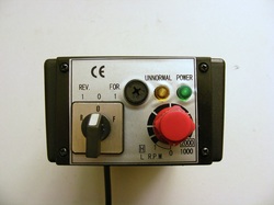
The controller rehoused in an ABS box. The lid is strengthened internally with a steel strip along the middle of the long axis so that it can be hung securely from the motor base plate. The cable entry is via a gland from underneath and the top has an IEC socket recessed into it.
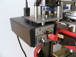
The motor mounted onto the motor plate and the controller attached underneath. Note the IEC motor plug inserted into the socket on top of the controller.
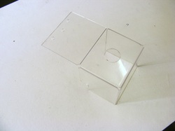
The protective guard was made from 2 mm Perspex sheet. This was cut to shape and bent using my plastics bender. The cover attaches to the hinge shown in earlier photos and is sandwiched between the hinge and the steel plate to minimise the risk of the Perspex cracking or splitting.
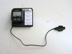
The tachometer is a cycle computer type AG11 from Wilkinsons (see here). it is attached to a steel angle bracket that bolts onto the motor plate. The sensor bolts onto the top plate with two M2.5 screws.
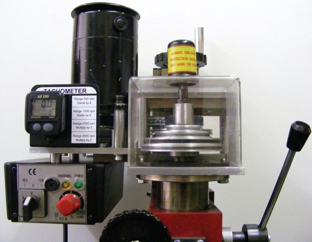
The tachometer records the speed of the layshaft rather than the spindle. I did this because the tachometer is only accurate up to speed of 2000rpm so it would not work for the 4000rpm speed. It is a simple matter to convert the layshaft speed to the spindle speed and a table of factors is printed at the side of the tachometer. The factors are easy to use since they are whole numbers ie. divide by 4, divide by 2, multiply by 1 and multiply by 2 for the ranges 0 - 500rpm, 0 - 1000rpm, 0 - 2000rpm and 0 - 4000 rpm respectively.
Note: The specified cycle computer has a direct readout in rpm. For models without this feature, program it with a wheel circumference of 1667 mm ( or the equivalent diameter = 530mm / 21") and set it to read in kph. Then, for example, a reading of 56.7 kph equates to 567 rpm
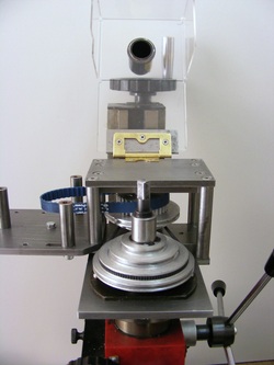
The completed conversion is shown in the header photo. The timing belt has only a light tension so that it puts little radial strain on the motor, The small vee belt is tensioned using the adjuster screw on the lower bearing plate which bears aginst the base plate and tightens the belt. Once the belt is tight then the two hex head M5 screws under the base plate are tightened down. To change speed takes about 1 minute. To change a belt it is necessary to remove the top plate but, hopefully, this will be a rare occurrance.
The mill is certainly much quieter with the belt drive and the highest speed is useful for small mills (less than 3 mm) whilst the slow speed is good for flycutting. The vee belt also protect the motor from severe overloads since it will slip if the load is excessive.
One possible improvement for the future is to add a substantial flywheel below the spindle pulley.
