Mill feedscrew bearing
The feedscrew bearings on the X1 mill are plain bushes and the thrust is taken on the feedscrew and handwheel running against the bearing block. This is not very satisfactory since it is difficult to eliminate backlash without the handwheel becoming quite stiff to turn. In addition the bearing block was beginning to wear badly due to the fairly large forces involved.
To solve this I decided to make new bearing blocks with preloaded ball bearings. This modification is very similar to that described by David White in Model Engineers' Workshop, Issue 150, May 2009. I, however, chose to use an aluminium casting rather than make it from 1.1/2" square aluminium.
To solve this I decided to make new bearing blocks with preloaded ball bearings. This modification is very similar to that described by David White in Model Engineers' Workshop, Issue 150, May 2009. I, however, chose to use an aluminium casting rather than make it from 1.1/2" square aluminium.
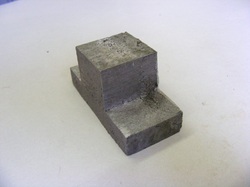
The bearing block was cast from a lost foam pattern. The central boss is 32 mm square and the flange 75 x 32 x 12 mm.
The casting did not turn out too well with a very rough surface but it seemed to be structurally sound so I carried on despite this.
The block was chucked in the four jaw chuck by the 32 mm square boss and the back of the flange faced. It was then turned around and held in the chuck by the flange and the boss faced off. The length from flange back to the front face was adjusted to be 35 mm (the same as the existing block).
The block was drilled through 13 mm and then bored out to 14 mm. A bearing recess was bored on the boss 22mm diameter and 7 mm deep. It was then turned around in the chuck and gripped by the boss and using a dti in the central bore was adjusted until it ran true. Then a second bearing recess was cut 22mm diameter and 17 mm deep.
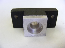
This shows the block after machining and a coat of paint. Note that the front top of the boss has been milled away a little to provide a flat surface for the index line against which the collar graduations can be read.
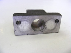
The rear bearing recess is 17 mm deep. With the bearing in place then the distance from the flange to the bearing is 10 mm. This is to keep the same position for the end of the leadscrew as in the original bearing block which are recessed to a depth of 10 mm.
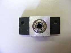
The bearings used are 608zz "skate" bearings. These are 22 mm OD, 7 mm thick and have an ID of 8 mm to match the feedscrew shaft.
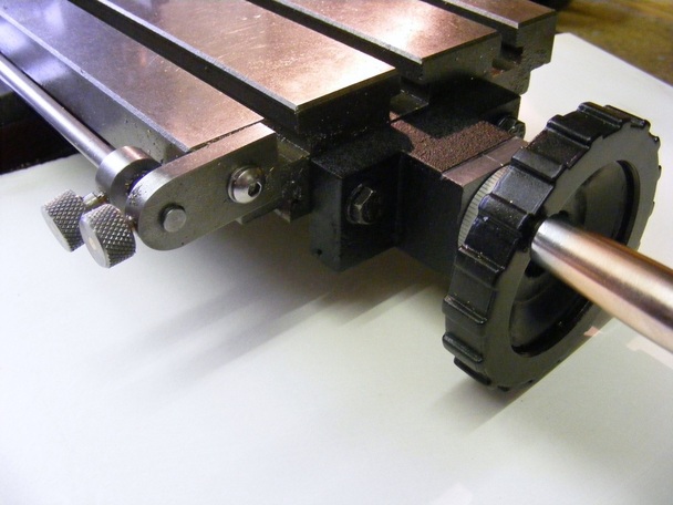
Once the bearings were pressed into position the unit was mounted on the mill as shown in the header photo. The hand wheel nut was tighted just sufficiently to eliminate any backlash.
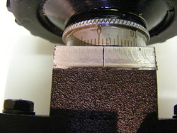
This shows the index line on the milled area at the front of the boss
This modification makes movement of the table using the handwheel much easier. Furthermore, when used in conjunction with the power feed modification the drive is much smoother and a greater range of speeds are usable.
