Mill quill lock lever.
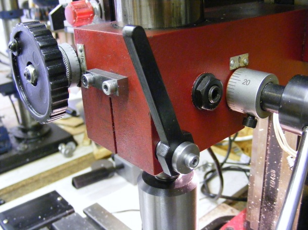
One of the annoying features of the X1 mill is that all the locks for the table and the quill require hex keys to operate them. I had previously modified the table locks so that they were lever operated (see here) but at that time I did not modify the quill lock. Frustration finally got the better of me and now a quill locking lever has been added.
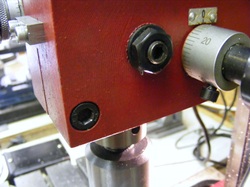
The original quill locking screw is the recessed M8 hex bolt at the bottom left of the headstock. Considerable force must be used to lock the quill so a sturdy and long lever is required.
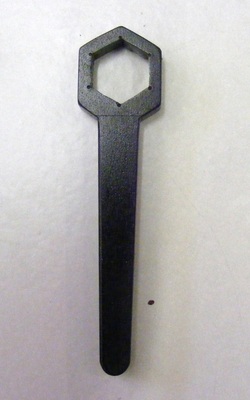
The lever was made from a piece of 6 x 19 x 80 mm steel. The centre of the bar was scribed with a line using jenny calipers and the centre of the hexagon punched 12 mm from one end.
A 15mm diameter circle was scribed using dividers. The two intersections of the centre line with the circle were then centre punched.
A part circle was scribed using the same divider setting with its centre at one of the new centre punch marks. The two points where the part circle and the full circle intersect were then centre punched.
This procedure was repeated using the other centre punch mark at the intersection of the full circle and the centre line as centre.
The six points marked should form a the corners of a regular hexagon. The remnants of these centre punch marks can be seen in the photo.
Re-punch the centre of the hexagon to provide a good start for a drill. Then drill a 12.5 mm diameter hole centred on this indentation. With a small square warding file the metal was filed away towards each of the centre punch marks. Once the hexagon starts to take shape then test periodically with the hexagon head of an M8 screw. Once the head starts to enter the hexagon hold the two pieces up to a light to see where the high points are. Continue filing until a good fit is achieved.
The lower end of the handle is 6 mm wide and the upper end is 10 mm wide. This shape was achieved by miilling. The final external shape was achieved by hacksawing and filing.
Heavily chamfer all the external edges with a file and then clean up the piece with emery cloth to give a smooth surface.
To finish the piece heat it up to red heat and plunge it into engine oil. This produces a relatively wear resistant black coating.
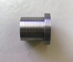
A stepped, threaded collar was made from 16 mm round steel. This is faced and turned down to 12 mm for a distance of 13 mm. It is drilled through with a 6.8 mm drill and partially threaded M8. The piece is parted off 16 mm from the end. The piece is then chucked by the narrow part, faced off. and counterboared 8.5 mm for a distance of 2 mm. After removal from the chuck the piece is held in the vice and threaded all the way through.
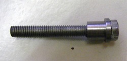
The stepped collar is then screwed onto an M8 screw. The screw is cut off to leave 50 mm of exposed thread below the collar.
The screw is then chucked in the lathe and a 3.3 mm hole drilled in the centre of the head for a depth of 13 mm. This is then tapped M4.
The screw is then chucked in the lathe and a 3.3 mm hole drilled in the centre of the head for a depth of 13 mm. This is then tapped M4.
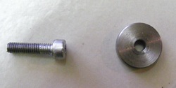
The final components are a M4 x 16 mm screw and a thick washer. The washer was made from 16 mm round bar. This was chucked in the lathe, faced, and drilled through 4 mm. It is parted of 4 mm from the end.
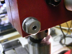
The new screw with the collar replaced the original M8 socket head screw as shown here.
Note the threaded M4 hole in the end of the screw.
Note the threaded M4 hole in the end of the screw.
The header photo shows the final assembled lever. The lever is slipped over the head of the M8 screw. There are six possible positions for the lever so choose an good position where the lever will not interfere with operation of the mill. The washer and screw are then used to clamp the lever in position.
